CENTRIFUGAL PUMP TYPES :
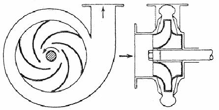
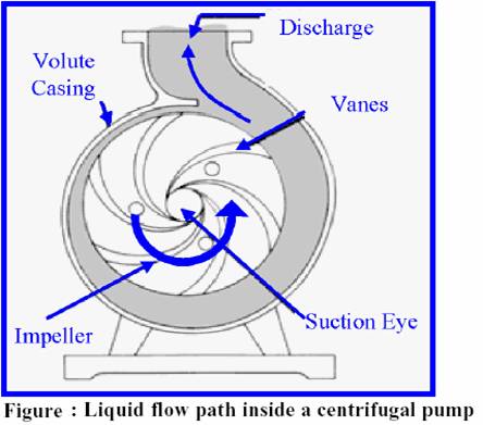
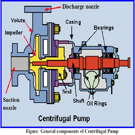
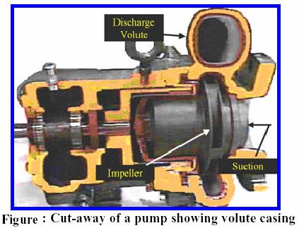
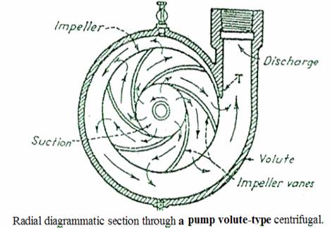
a) Volute Type - The volute pump is so called because of the shape of the casing, in the form of spiral - volute gradually increasing section which acts as a collector for the fluid discharged by the impeller. The object of the volute is gradually to reduce the velocity of the water after it leaves the impeller and so convert part of its kinetic energy to pressure energy. For general purposes the volute pump is commonly used.

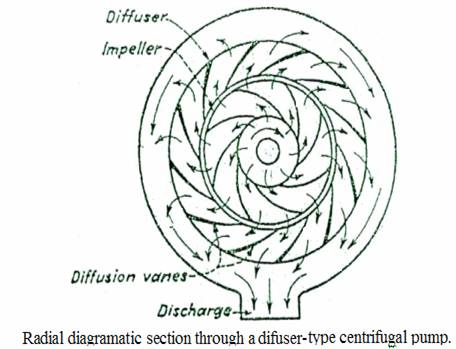
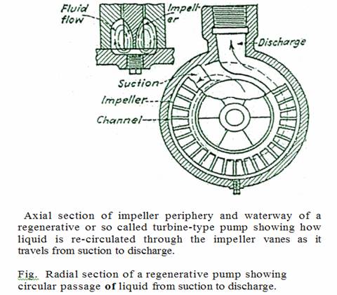
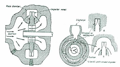
Fig 11.1 Fig 11.2
Fig 11-1 Cross section through regenerative pump showing flow from suction to impeller vanes.
Fig 11-2, Radial section through regenerative pump showing path of liquid with auxiliary axial sections at stripper or sealing wall (A) and at suction passages (B).
Diffuser Type - The diffuser pump is so called because of the ring of the guide diffuser vane passages around the impeller. The design is used for high pressure as in multi - stage boiler feed pumps. The diffuser passages are able to convert a large amount of the kinetic energy of the liquid as it leaves the impeller into pressure energy.
b) Regenerative/Turbine - Type - The term turbine - pump of centrifugal design is generally called "diffuser type", except for the vertical turbine pumps. Multi – stage deepwell pumps for bulk liquid cargoes may be referred to as turbine pumps.
In regenerative pump, the impeller with vanes cut in its rim that rotate in an annular channel or race chamber. Liquid entering the casing flows to both sides of the impeller to give-hydrantic balance and a double - suction effect. Twin passages lead the liquid to the impeller blades. Each casing is equipped with a dividing wall or stripper, through which the impeller passes with close clearance. Just, beyond the wall in the direction of rotation, twin suction passages pass around the sealing wall and come into the impeller chamber. The impeller blades pick up the liquid as it comes from the suction passage and centrifugal force throws it out to the periphery of the impeller. Liquid leaving the impeller blades has velocity energy added. The casing passage causes a gradual reduction of velocity with the accompanying increase in potential energy (pressure).
In the impeller the vane - support shape is such as to cause the liquid leaving to rotate. Casing passage shape continues the rotary motion as the velocity of the liquid decreases until at low velocity the liquid is guided back into the impeller blades, the liquid then repeats the cycle and again adds energy or generates head. This regeneration of head from which the pump gets its name. The pumps are used where a relatively high pressure and small capacity are required. The regenerative pump is self priming and can handle vaporizing liquid.
