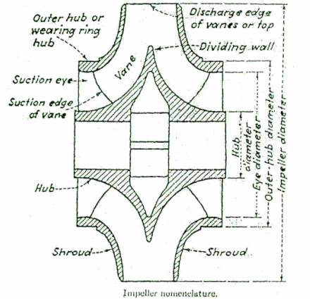
STAGE/SUCTION/VOLUTE:
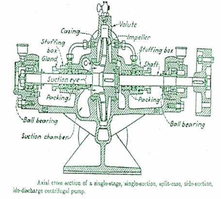
A single stage centrifugal pump is one in which the total head is developed by a single impeller.
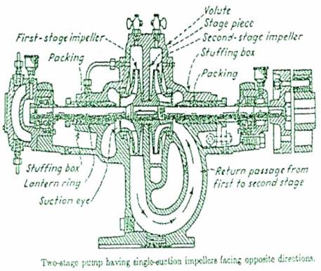
If the total head required is too high for a single impeller to produce, two or more impellers may be used in services, the second impeller taking its suction from the discharge of the first impeller. If all impellers acting in services are in a single casing, the pump is a multistage design.
A single - suction impeller is one in which the liquid pumped enters the impeller from one side only.
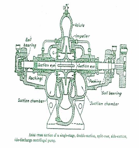
A double - suction impeller is, in effect, two single - suction impellers cast back-to-back so that liquid enters the impeller simaultaneously from both sides. Normally, the suction chambers, one at each side of the impeller, connect to a common suction passage and nozzle.
In general service, a double-suction impeller is favoured in single-stage, horizontally split casing designs. It is theoretically in axial hydraulic balance, making an oversized thrust bearing unnecessary. The greater suction area in a double - suction impeller permits the pump to operate with less net absolute suction head for a given capacity than with a single - suctions impeller. For manufacturing reasons, the single - suction impellers are more practical than the double - suction in small pumps because the waterways are double size and not divided into two, but they require a large thrust bearing to take the

unbalanced axial thrust or balancing ports. Pumps with radially split casing with single-suction mostly have overhang impellers where the shaft does not extend to suction eye.
OPEN IMPELLER:
An open - impeller has vanes only, attached to a central hub without any form of side wall or shroud. With long vanes this design is structurally weak, and the vanes have to be strengthened by ribs or partial shrouds. Generally open impellers are used in small
inexpensive pumps or in those handling abrasive liquids. The impeller rotates between side plates in the volute - casing walls or between the stuffing box and suction - head covers. Because of the clearance between impeller vanes and side walls, water shippage occurs, similar to that in a reciprocating-pump, which increases with wear. Restoring the original efficiency requires replacing both the impeller and the side plates, which costs more than replacing sealing rings in a closed - impeller pump.
SEMIOPEN IMPELLER:
It has a shroud or wall on one side only. The shroud may or may not have vanes for pumping out fluid to reduce pressure on the stuffing box of single - suction pumps and to prevent solid materials from lodging behind the impeller.
CLOSED IMPELLER:
The design used almost universally, in centrifugal pumps handling clear liquids, has shrouds on each side that totally enclose the waterways from the suction eye to the periphery of the impeller. Water slippage does not occur in the design as with an open or semi - open impeller, but a sealing ring is needed fitted over the suction eye shroud and rotates with a very fine clearance with the pump casing.
Straight Vane impeller is one in which the vane surfaces are generated by straight lines parallel to the axis of rotation, vanes of this design are also called single curvature vanes.
In Francis - screw - vane impellers, the vane surfaces have a double curvature, one at the suction - eye and the other leading to the outer periphery.
In multi - flow impeller, the flow is both radial and axial. It is generally restricted to single - suction design having a specific speed above 4200. Lower specific speed types are called 'francis - screw - vane'. Mixed - flow impellers having a small radial - flow component are generally classed as propellers.
An axial flow impeller is one having a flow solely parallel to the axis of rotation i.e. strictly axial.
RADIAL THRUST :
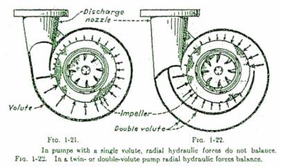
In a single - volute centrifugal pump, fluid discharged by the impeller into the volute produces hydraulic force that act radially on the impeller, as indicated by arrows in the figure. The forces are not equal around the impeller and consequently produces a radial thrust that is transmitted to the shaft.
Single Volute Pump - A single volute completely surrounds the impeller, and radial hydraulic forces do not balance, causing a resultant force that acts radially on the shaft.
Twin Volute Pump - A twin volute is, in effect, two half - capacity volutes, each taking the
discharge from 180 degree of the impeller in a way that approximately balances the radial thrust. It is sometimes used in single - stage pumps, particularly those of large capacity for high heads and in multistage pumps developing high heads per stage.
Twin - volute diffuser - It is in effect, a twin volute but cast separately from the casing. It resembles a diff user with only two vanes and is used mainly on multistage pumps where the diffuser also contains the return channel to the stage that follows.
WEARING RINGS:
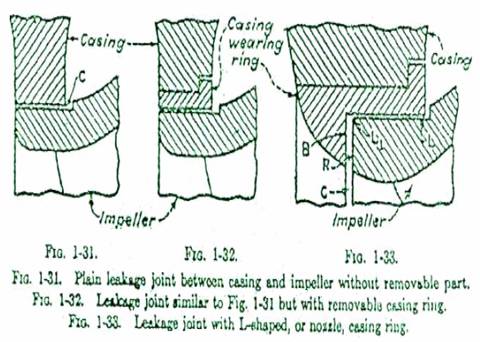
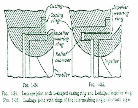
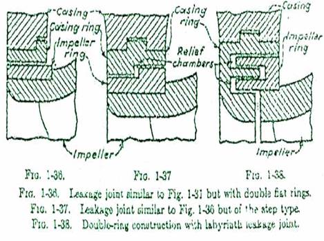
In a centrifugal pump, there is a running joint formed by a portion of the impeller and a portion of the casing, separating the chambers forming suction and discharge waterways. The leakage of liquid through this running clearance joint will cause wear on the adjacent surfaces, the rate of wear being greater if there is grit or other foreign material in the liquid. At the same time, if the clearance is more at the running joint, then leakage between discharge and suction reduces the throughput of the pump.
In most pump design, either a removable casing wearing ring also called a 'impeller guide ring' is inserted in the pump casing to protect the latter from wear, or an impeller wearing ring (removable) fitted on top of the impeller suction eye to protect it from wear. These removable wearing rings can be replaced when worn at a fraction of the cost of a new casing or impeller. Since the amount of leakage through a clearance joint is controlled by its area, the length oHhe path and the differential pressure, its logical position is impeller eye where the diameter, area and length is minimum. These wearing rings are fitted on to the impeller eye by shrunk fit or by sets crews, for easy removal in case of replacement.
STATIC & DYNAMIC BALANCE, CRITICAL SPEED :
A pump rotor is in static balance if, when supported on parallel and level knife edges or their equivalent, it will remain stationery in any position in which it may be placed.
A pump rotor is in dynamic balance if all the various centrifugal forces resulting from its rotation balance each other. Such a rotor runs at full speed without vibration
Any object of elastic material has a natural period of vibration. If a pump rotor or shaft rotates at a speed corresponding to its natural frequency, any minor unbalance is magnified. Such speeds are called critical speeds. The lowest is called the first critical, the next higher, the second, etc. When the rotor of a centrifugal pump operates at its critical speeds, it vibrates excessively, its shaft deflections exceed internal clearances, and the shaft may fail.
RIGID & FLEXIBLE SHAFTS:
A rigid shaft has a first critical speed higher than its operating speed.
A flexible shaft has its operating speed higher than one of its critical speeds.
STUFFING BOX:
A stuffing box is an arrangement fitted on the pump shaft at a place where the pump shaft comes out of its casing. When the pressure at the pump suction end is below atmospheric, the stuffing box prevents air leakage into the pump. When the pressure at its inner end is above atmospheric, the stuffing box prevents liquid leaking out of the pump.
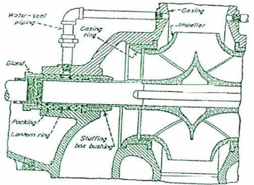
Partial section of a double suction pump to show stuffing- box"bushing and other stuffing box details
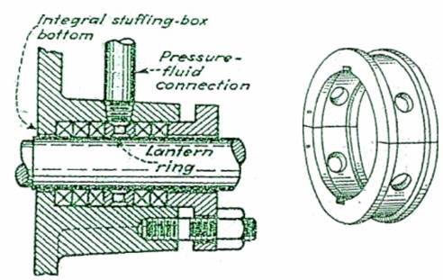
Fig section of stuffing box with integral bottom. Fig Typical lantern ring
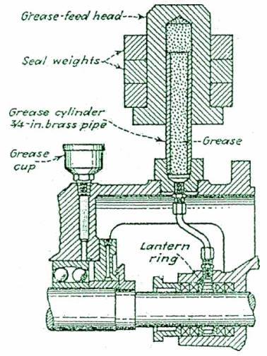
A stuffing box consists of a bushing which forms the stuffing - box bottom, which may be integtral with the casing, or independent and split into two halves for easy removal from shaft. A lantern ring which forms a water-seal cage having a small pipe - connection from the discharge side and makes an effective seal beyond which air cannot pass into the pump. The seal chamber also provides a reservoir of water or fluid for cooling and lubricating the packing against friction with the shaft. A soft packing material is used tightened by a gland to prevent leakage along the shaft.
AXIAL HYDRAULIC THRUST:
It is the summation of unbalanced forces acting on an impeller in an axial direction. Single - suction impellers, if wearing rings are not provided in the back, are subjected to an axial thrust.
Axial thrust balancing can be achieved by providing wearing rings of the same inside diameter on the suction and back sides of the impeller and having balancing hole through the latter. In multi - stage pumps, all impellers may face in the same direction and the pump be provided with a hydraulic balancing device. An alternative, an even number of impellers may be used and divided into two equal groups. The two groups face in opposite directions so that the axial thrust is practically balanced.
In modern practice, a combination of balancing drum and balancing disk is fitted on the shaft at the end of the stage, and the balancing chamber beyond the last - stage impeller is separated from the pump discharged by the radial clearance of balancing drum and axial clearance of the balancing disk. The balancing chamber is connected to the pump suction or suction source. This drum and disk arrangement maintains the balancing chamber in such a manner that the axial thrust is completely eliminated.