Question
a) With reference to the importance of good
design and a high standard of workmanship in the fitting and repair of bilge
keels.
(i) Describe how
the design and method of attachment reduces the possibility
of damage to the
shell plate:
(ii) State the authority the must be afforded
the opportunity to inspect the fitting and repair:
(iii) State what non-destructive testing is
carried out
(b) Explain why
bilge keels do not extend for the full length of the ship:
Answer.
(a)
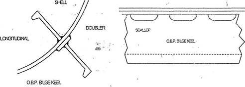
(i) The bilge keels are
attached directly in line with internal stiffening such as a girder or
longitudinal. On thicker shell plating (such as merchant ships) the bilge keel
is made up of a flat bar doubler welded directly to
the shell and an offset bulb plate (OBP) with 'scallops' cut in it is welded to
the flat bar doubler. The ends of the bilge keels are
tapered and if the keels are positioned so that they follow the streamlines at
the service speed of the ship, then the added resistance is only about 2%.
(ii) The Authority that must be afforded the opportunity
to inspect the fitting and repair is the Load Line Assigning Authority Surveyor
(e.g. the Lloyds Register Surveyor)
(iii) The non-destructive testing that must be carried
out is either X-ray or ultrasonic.
(b) Bilge keels are not fitted for the full length of
the vessel because:
(i) The lever to the ships
axis of rotation is reduced at the ends;
(ii) It would be more difficult to make and fit due to
the bending and twisting
required:
(iii) It would be difficult lo align with flow along
the hull, particularly at the fore end.
The hydrodynamic effect would cause a large increase
in resistance and fuel
consumption:
(iv) At the aft end the boundary
layer is much thicker and since the keel would not project through, it would
have much reduced effect