1.
Explain how rotating magnetic field is produced in 3 phase winding
with 3 phase supply?
The three phase windings are displaced in space by 120º, and are fed by three phase currents, displaced in time by 120º. This combination produce a resultant magnetic flux, which rotates in space as if actual magnetic poles were being rotated mechanically.
The flux due to the three phase windings are assumed sinusoidal. Let the maximum value of flux due to any one of the three phases be Øm. the resultant flux Ør, at any instant is given by the vector sum of the individual fluxes Ø1, Ø2 and Ø3 due to three phases. Let us consider the values of resultant flux at four instant, 1/6th time period apart .(i.e. 60º apart)
At
the instant time period is zero, Ø1 = 0, Ø2 = - √3/2 Øm, Ø3 = +√3/2
Øm'
Hence, Ør = 2 x √3/2 Øm cos 60º/2 = √3 x √ 3/2 Øm = 3/2 Øm
At the instant time period is 60º, Ø1 = +√3/2 Øm' Ø2 = - √3/2 Øm, Ø3 = 0
Hence, Ør = 2 x √3/2 Øm
cos 60º/2 = √3 x √ 3/2 Øm =
3/2 Øm
It is seen that the resultant flux is again 3/2 Øm, but has rotated clockwise through an angle of 60º.
At the
instant time period is 120º, Ø2 = 0, Ø3 = - √3/2 Øm, Ø1 = +√3/2
Øm'
Hence, Ør = 2 x √3/2 Øm
cos 60º/2 = √3 x √ 3/2 Øm =
3/2 Øm
It is seen that the resultant flux is again 3/2 Øm, but has further rotated clockwise through an angle of 60º.
At the instants when time period is 180º,240ºand 360º it can be further proved that resultant flux is same (3/2 Øm,) but rotating through an angle of 60º further to the previous time period.
Hence the resultant flux is of constant value 3/2 Øm, but rotating around the stator at synchronous speed given by Ns = 120 f / P.
2.
Compare the series and parallel resonance circuits? Draw impedance
characteristics of the circuit?
|
Series
resonance |
Parallel
resonance |
|
at
resonance, net reactance is zero. XL =
XC circuit
impedance is minimum, Z = R consequently the circuit admittance is maximum circuit
current is maximum and is given by V/R power
dissipated is maximum, V2/R power
factor is unity Voltage
across the coil is higher than the voltage across the capacitance due to its
resistance. resonant
frequency = 1 / 2π√ LC it
is an acceptor circuit the
series resonance is referred as voltage resonance |
1. net susceptance is zero L/C = Z2 2. the admittance equals conductance 3. reactive or wattless component of the line
current is zero. 4. dynamic impedance =
L/CR ohms 5. line current is minimum and is in phase
with applied voltage. 6. power factor of the circuit is unity. 7. it is an rejector circuit. 8. the parallel resonance is referred as
current resonance 9. the current circulating between the two
branches is many times greater than the line current taken from the supply. 10. resonant frequency =
|
3.
What are the losses in transformers? Mention the various factors
which affect these losses?
The losses in the transformer are grouped into 1. Iron losses and 2. Copper losses.
Iron losses comprise of Hysteresis loss and Eddy current loss. Hysteresis loss is due to the reversal magnetization in the core, as the supply being alternating current and reversal takes in each cycle. This loss depends on the volume and grade of iron, maximum value of the clux density and frequency of magnetic reversals.
Wh = η B1.6maxf V watts. (Steinmetz formula)
Bmx = maximum flux density, f = frequency, V = volume of core in m3 .
Eddy current loss is due to the current setup by the induced emf in the core, which circulates in the core itself. The power loss (which is in the form of heat) due to this current is known as eddy current loss. The loss would be considerable if the core is of solid one. In order to reduce this loss and the consequent heating of the core to a small value, the core is built up of thin laminations, which are stacked and riveted or bolted at right angles to the path of eddy currents. These core laminations are insulated from each other by a thin coating of varnish.
We = K B2 f2 t2 V2.
B = flux density, K = a constant, f = frequency, t = thickness of lamination, V = volume of the core in m3.
This loss varies directly as the square of the thickness of laminations, square of the frequency of supply voltage and square of the volume of the core. The thickness of the lamination is kept to a minimum to reduce the eddy current loss.
Iron loss remains constant irrespective of the load. Normally iron loss is found out in the no load test.
Copper losses: This loss is mainly due to the current carried in the winding and is identified as I2R loss. The no load copper loss is normally negligible, as the no load current in the primary is of 1 to 2% of full load current. The copper losses become appreciable on load. This depends on the resistance of the winding and the current carried by it. Resistance in-turn depend on the length and area of cross section of the wire and also the operating temperature.
4.
Explain the significance of RMS values of an AC current or voltage
wave form. Define the form factor of such a wave form?
The root mean square value
of an alternating current or voltage is of considerable importance in practice,
because the ammeters and voltmeters record the RMS value of alternating current
and voltage respectively. In electrical
engineering work, unless indicated otherwise, the values of given current and
voltage are always the RMS value. It is
the effective or virtual value. This is
the steady (
The form factor is
defined as the ratio of RMS value to the average value. Its numerical value is 1.11. the form factor enables the r.m.s value to be
found from the arithmetic mean value and vice versa.
5.
Show how the power that is transferred across the air gap of the 3
phase induction motor is represented? Explain the terms. What portion of this
is useful power?
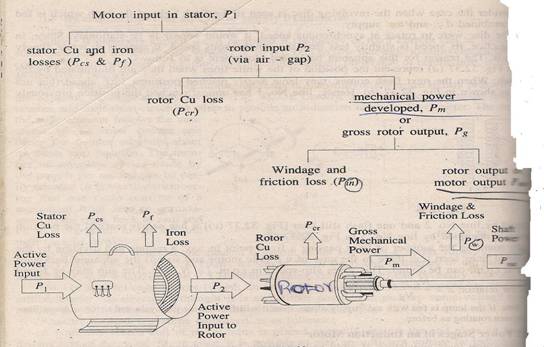
The available power at the rotor (shaft) is the useful power. That is Shaft power Pout.
This Pout. Will be less than Pm (mechanical power developed or gross rotor input) due to windage and friction losses of the rotor.
Moto input power is due to the mains supply voltage.
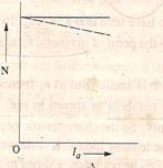
6. Explain the preference for a 60 hz system . Describe the dangers of running a 50 hz system from a 60 hz supply.
the number of revolutions that an electrical motor turns is
dependent upon the cycles per second (Hertz) that the alternating current is
changing. A motor that is designed to run on 60 Hz and is plugged into a 50 Hz
system will turn 17% slower, the internal current will go up 17%, the amount of
power (watts) will go down 17%, and the mechanical cooling will be 17% less.
The end result will be that the motor will be using a higher current then what
the motor was designed for, and this in turn will burn up the insulation of the
electrical wiring which can result in burnout which could cause a fire because
of the excessive heat.
Induction motors use an iron core and require flux in the iron to operate. In order to achieve the commercial goals of smallest size and lowest price at best efficiency, induction motors are designed to operate at a high level of flux in the iron. The flux is determined by the turns, voltage and frequency. In a modern motor, if the flux is increased by a small amount, the iron losses increase and the iron tends towards saturation. At saturation, the inductance begins to fall and the current increases further. To reduce the flux at a given voltage and frequency, the turns on the stator are increased. This reduces the Iron loss, but a longer length of thinner wire is used and the copper loss increases. Design becomes a balancing act between copper loss and iron loss and so the design is optimised for a given voltage and frequency.
If the voltage applied to the motor is held constant and the frequency is increased, the inductive reactance increases and so the flux reduces. This effectively reduces the maximum torque capacity of the motor and so the motor power rating at the higher frequency remains the same.
If the voltage applied to the motor is held constant and the frequency is reduced, the current will increase and in theory, the torque will also increase. The motor should be able to deliver the same power also, BUT the flux in the iron is now too high resulting in excessive iron loss, and the motor will fail prematurely. Above a very low frequency, (5 - 10Hz) the impedance of the magentising circuit of the motor is primarily inductive and so in order to keep the flux within limits, it is important to keep a linear V/F ratio (Voltage to Frequency ratio). If the frequency is reduced by 10%, the voltage must also be reduced by 10%. Because the flux in the iron remains the same, the torque capacity remains the same and so the power rating of the motor also drops by 10%.
Provided the voltage is dropped by the same proportion as the frequency, it is OK to run a 60Hz motor on 50Hz. The speed will be reduced by the reduction in frequency and the power capacity will also reduce by the reduction in frequency.
|
60 Hz Volts |
50 Hz Volts |
|
480 |
400 |
|
460 |
383 |
|
440 |
367 |
|
230 |
191 |
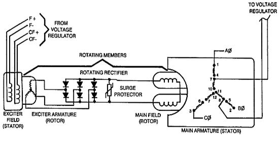
7. What is dc alternator? How is an direct connected exciter arranged in an alternator?
A brushless
alternator is composed of two alternators built end-to-end on one shaft.
Smaller brushless alternators may look like one unit but the two parts are
readily identifiable on the large versions. The larger of the two sections is
the main alternator and the smaller one is the exciter. The exciter has
stationary field coils and
a rotating armature (power coils). The main alternator uses the opposite
configuration with a rotating field and stationary armature. A bridge rectifier, called the rotating rectifier
assembly, is mounted on a plate attached to the rotor. Neither brushes nor slip
rings are used, which reduces the number of wearing parts. The main alternator
has a rotating field as described above and a stationary armature (power
generation windings).
Varying the amount of
current through the stationary exciter field coils varies the 3-phase output
from the exciter. This output is rectified by a rotating rectifier assembly,
mounted on the rotor, and the resultant DC supplies the rotating field of the
main alternator and hence alternator output. The result of all this is that a
small DC exciter current indirectly controls the output of the main alternator.
8.
Explain the potential hazards if liquid cooled transformers are
used?
a. Oxidation and moisture are may cause deterioration, leading to insulation failure.
b. due to temperature rise, possiblilty of development of flammable vapours.
c. Release of toxic vapours.
d. Inoperative gauges and alarms. Transformer gauges and
alarm devices are generally ignored until there is a problem with the transformer.
As a result, gauges are often difficult or impossible to
read due to a build-up of dirt. Gauges can be out
of calibration, thus giving faulty readings. Alarm contacts can be corroded,
failing to trigger the alarm when conditions warrant. The glass in liquid
level indicators can be dirty, making it
impossible to determine the coolant level. Test and calibrate all alarms and
gauges as necessary.
e. Insufficient capacity. If a transformer
overheats under heavy load conditions, it can be caused by a defective cooling
system, a failing transformer, or electrical overloading.
f. Leaks. Any leak of
insulating fluid from a transformer is potentially serious. If leaks are
allowed to continue uncorrected, they can cause sections of the transformer’s
core to become exposed, resulting in
overheating and accelerated deterioration.
g. Mounting pad damage. Settlement, movement,
cracking or breaking of the transformer’s concrete mounting pad can result in
an uneven shifting or settlement of the transformer, stressing connections..
h. Overheating.
Overheating is the principal cause of insulation breakdown in transformers. Using
an infrared detector, check the transformer and its connections for hot spots.
Hot spots in the transformer contribute to the breakdown of the transformer’s
insulation.
9. List factor that determine the starting torque of a 3 phase induction motor. How this torque does generally compared with the value of the rated torque?
The torque developed by
asynchronous induction motors varies with the speed of the motor when its
accelerate from full stop or zero speed, to maximum operating speed.
The starting torque of an induction motor can vary from as low as 60% of full load torque to as high as 350% of full load torque. Starting torques for medium to large motors are in the order of 120% of full load torque to 280% of full load torque. The PF of the motor at start is typically 0.1-0.25, rising to a maximum as the motor accelerates and then falling again as the motor approaches full speed. Normally it will be 1.5 times the full load torque even though the current may be 5 to 6 times the full load current.
10.
State the basic equation from which delta –star & star- delta
conversion equation can be derived.
In a 3 phase circuit, the three phase windings are kept 120°(electrical) apart.
Assuming the waves in the three windings to be sinusoidal and counting the tiem from the instant when the emf in phase ‘a’ is zero, the instantaneous values of the three emfs will be given curves, whose equations will be ea = Emsin(ω t)
eb = Emsin(ω t - 120°)
ec = Emsin(ω t - 240°)
these voltages may be represented by revolving vectors which indicate their maximum values (or rms values). The actual values of these voltages vary from peak positive to zero and to peak negative values in one revolution of the vectors. It will be seen that the sum of the above three equations will be zero.
This forms the basic criteria for star-delta
or delta –star conversion.
11.
Explain what is meant by the term 1. Wave form 2. Frequency 3.
Average value?
1. Wave form: The shape of the curve obtained by plotting the instantaneous values of voltage or current as the ordinate against time as abscissa is called its wave form
2. Frequency : The number of cycles / second is called the frequency of the
alternating quantity. Unit Hz.
3. Average Value: the average value of an alternating current is expressed by that steady current which transfers across any circuit the same charge as is transferred by that alternating current during the same time. Average value = 0.637 x maximum value
12.
Why is
it important to maintain high efficiency of operation and low values of voltage
regulation for power transformers?
Efficiency of a transformer (or for that matter any machine) = output / input
= output / output + losses.
The losses in the transformer are copper losses and iron losses. Iron loss is always remain constant (design factor), but copper losses vary with the load current. Efficiency becomes maximum when copper losses become equal to iron losses. It is always preferable to operate the machinery at high efficiency, so that the losses are minimum, heating effect is minimum, more output is obtained.
In case of transformer when load increases, the terminal voltage on the secondary decreases (assuming the load is connected to the secondary side), due to its internal resistance and leakage reactance. The regulation is nothing but the difference in no load terminal voltage on the secondary and the terminal voltage of secondary on load, expresses as %. If the voltage drop is more on load conditions, then the secondary current has to increase to meet the load or the primary voltage has to increase to meet the requirement. In both cases the copper losses will increase, which will affect the efficiency.
Low voltage regulation means, the drop in secondary terminal voltage on load is quite low. If the power transformer is to be operated at high efficiency, then the voltage regulation has to be low.
13.
What is effect on the field flux of an alternator current in the
synchronous motor that leads the terminal voltage?
This condition refers to that of over excitation. When running on light load, the torque angle α1 is small, but armature current Ia1 is comparatively larger and leads terminal voltage V by a larger angle Ф1. When more load is applied, the power factor improves and approaches unity. The armature current also increases thereby producing the necessary increased armature power to meet the increased applied load. The power factor angle Ф decreases (p.f. increases) at a faster rate than the armature current thereby producing the necessary increased power to meet the
Increased 
14.
Describe the effect of following load on power factor a) induction motor b) transformers c )
partly loaded motors d) cage type motors?
15.
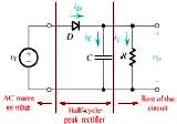
By means of a schematic circuit diagram illustrate the peak
rectifier? If the supply voltage is v (t) = Vm sin wt ,what is the voltage
across the load resistor?
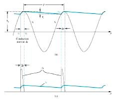
The output of the rectifier circuits is always pulsating with respect to time. DC power supply required should have minimum pulsation or ripple. This is achieved by adding a filter circuit in the output side. In peak rectifiers a capacitor filter is used, the value is such a way chosen as to make the ripple as minimum as possible.
Sizing of the capacitor represents a trade off. For a given load,
a larger capacitor will reduce ripple For a given tolerable ripple the required capacitor size is
proportional to the load current and inversely proportional to the supply
frequency and the number of output peaks of the rectifier per input cycle. The
load current and the supply frequency are generally outside the control of the
designer of the rectifier system but the number of peaks per input cycle can be
affected by the choice of rectifier design.
A half-wave
rectifier will only give one peak per cycle and for this and other reasons is
only used in very small power supplies. A full wave rectifier achieves two
peaks per cycle and this is the best that can be done with single-phase input.
For three-phase inputs a three-phase bridge will give six peaks per cycle and
even higher numbers of peaks can be achieved by using transformer networks
placed before the rectifier to convert to a higher phase order.
The supply voltage
is v (t) = Vm sin wt
The maximum value of pulsating output is Vm and the dc component V’dc = 2 Vm / π in case of full wave rectifier and in case of half wave rectifier V’dc = Vm / π.
If any DC resistance(R) comes across in the circuit in series with the load resistor(RL) then the output voltage across the resistor will be
Vdc = [V’dc /( R + RL)] x RL
{ Sketch and illustrate a PEA
rectifier. If supply voltage v(t) =Vm
sinωt, what is the voltage across
the load resistor.
PEA means power electronics application. Rectifier using SCRs can be shown. The output voltage across the load resistance
in case of full wave rectification will be
Vav = (Vm/π ) (1 + cosα) and Iav = (Vm/πRL) (1+
cosα) where α is the firing
angle for the thyristor and the conduction angle will be (180° - α)}
16.
Which of the following 3 motors has the poorest speed regulation
shunt motor, series motor, or cumulative compound motor? Explain
Speed regulation means change in speed of a motor with change in applied load torque, other conditions remaining constant.
Shunt motor is almost a constant speed motor on load.
Series motor, the speed is very high on no load and speed is less on load. Series motor can not be started without load.
Compound motor is in between, and is used where both speed and torque has to match for maximum output.
Hence series motor has the poorest speed regulation.
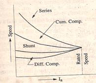
Series motor all three motors shunt motor
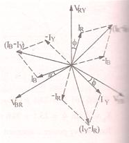
17. Derive the expression for current and voltage relations between line and phase values in the star and delta cases. Draw the vector diagram?
STAR CONNECTION:
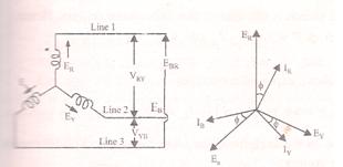
Indication of various phase and line parameters vector or phasor diagram for derivation
(the faded one EB and on the right read Ea as EB)
the windings are 120° out of phase with each other. The vector sum of the currents meeting at the neutral is zero. i.e. IR + IB + IC = 0
the voltage induced in each winding is called the Phase voltage and current in each winding is like wise known as phase current. The voltage available between any pair of te3rminals is called line voltage VL . there are to phase windings between each pair of terminals, but since their similar ends have been joined together, they are in opposition. Obviously, the instantaneous value of p.d between any two terminals is the arithmetic difference of the two phase emfs converned. However the rms value of this p.d. is given by the vector difference of the two phase emfs.
ER,, EY, EB are phase emfs. For a balanced load ER = EY = EB
Line voltage VRY between line 1 and line 2 is the vector difference of ER and EY
Line voltage VYB between line 1 and line 2 is the vector difference of EY and EB
Line voltage VBR between line 1 and line 2 is the vector difference of EB and ER
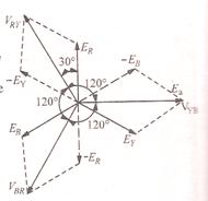
The p.d. between line 1 and 2 is VRY = ER - EY
Hence VRY is foundby compounding ER and EY reversed and its value is given by the diagonal of the parallelogram on the right side figure. The angle between ER and (EY reversed) is 60°.
VRY = 2 x EPH x cos (60°/2)
= 2 x EPH x cos 30°
= 2 x EPH x √3/2
= √3 EPH
Similarly VYB = EY - EB = √3 EPH
VBR = EB - ER =
√3 EPH
Current in line 1 = IR, current in line 2 = IY and the current in line 3 = IB
Since IR = IY = IB = IPh say, ( remember, the current through the winding of one phase is flowing through the corresponding line, same winding extends to the line)
Hence IL (line current) = IPh (phase current)
Power: the total power is power produced by 3 phases
Hence power = 3 VPh x IPh x cos Ф
= 3 x VL / √3 x IL x cos Ф
= √3
DELTA CONNECTION:
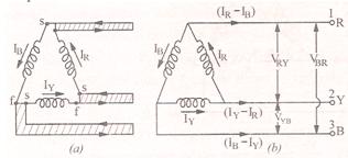
For delta connection VRY = VYB = VBR = phase voltage = line voltage (voltage across each winding which constitute a phase)
But the line currents will be the vector difference of phase currents.
For example I1 = line current in 1 = IR - IB (where IR and IB are phase currents)
I2 = line current in 2 = IY - IR (where IY and IR are phase currents)
I3 = line current in 3 = IB - IY (where IB and IY are phase currents)
Working in the similar way as done for star connection, it will be found that
I1 = 2 x IPh x cos 60°/2 = 2 x IPh x √3/2 = √3 IPH
Hence in delta connection, line voltage = phase voltage
Line current = √3 x phase current
Hence power is 3 VPh x IPh x cos Ф or = 3 x VL x IL/ √3 x cos Ф = √3 VL IL cos Ф
18.
What is slip? What are the factors on which the torque of an
induction motor depends?
Slip is the difference between the synchronous speed and the actual speed of the rotor when the motor is on load.
Sometimes slip speed is called the difference between the synchronous speed and actual speed (NS - N)
Rotor speed is N = NS (1 – s) where s = slip
Torque equation is given by
T = k x E2 x I2 x cosФ2
The subscript 2 are indicating the rotor condition.
Torque depends on the rotor induced emf, the rotor current and the power factor (cosine of the phase angle of rotor induced emf and the rotor current)
These parameters again depend on rotor resistance and reactance. The resistance of squirrel cage rotor is almost constant and low compared to its reactance during start. But when running as slip reduces, the reactance drops. Hence the power factor, rotor induced emf and rotor currents will change for starting and running conditions.
19.
How does change in frequency effect operation of Trans formers. What
make this ratio different from the ratio of transformation?
The core loss of a transformer depends on the frequency and the maximum flux density for a given volume and the thickness of the core laminations. The hysteresis loss is proportional to (frequency) and the eddy current loss is proportional to the (frequency)2. The total core loss is the sum of hysteresis and eddy current losses. Hence the efficiency of transformer is affected.
Change in the frequency changes the induced voltage as E = 4.44 f φ N
20.
Discuss the different method of speed control of dc series motor by
adjusting field ampere turns?
Field diverters
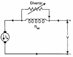
In this
method, a variable resistance (called field diverter) is connected in parallel
with series field winding as shown in Fig.(5.6). Its effect is to shunt some portion
of the line current from the series field winding, thus weakening the field and
increasing the speed(N ∝ 1/ φ).
The lowest speed obtainable is that
corresponding to zero current in the diverter (i.e., diverter is open). Obviously, the lowest speed
obtainable is the normal speed of the motor. Consequently, this method can only
provide speeds above the normal speed. The series field diverter method is
often employed in traction work.
Armature diverter:
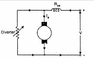
In order to obtain speeds below the normal
speed, a variable resistance (called
armature diverter) is connected in parallel with the armature as shown in Fig. The diverter shunts some of the line
current, thus reducing the armature current. Now for a given load, if Ia
is decreased, the flux φ must increase ( T∝ φIa). Since N ∝ 1/ φ , the motor speed is decreased. By adjusting the armature
diverter, any speed lower than the normal
speed can be obtained
Tapped field control:
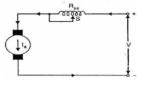
In this method, the flux is reduced (and hence speed is increased) by decreasing the number of
turns of the series field winding as shown in Fig. . The switch S can short
circuit any part of the field winding, thus decreasing the flux and raising the
speed. With full turns of the field winding, the motor runs at normal
speed and as the field turns are cut out, speeds higher than normal speed are
achieved.
Paralleling field coils:
This method is usually employed in the case of fan motors.
By regrouping the field coils as shown in Fig. (5.9), several fixed speeds can be
obtained.
21.
What are the factor which determine the synchronous speed of a
motor?
The speed of the synchronous motor depends on the supply frequency and the number of poles. Ns = 120 x f / P where f is the supply frequency and P number of poles and Ns being the synchronous speed.
22.
Explain the purpose of interlopes and state their magnetic polarity
relative to the main poles both generators and motors?
The interpoles (also known as compoles) are fixed to the yoke and spaced in between the main poles. They are wound with comparatively few heavy gauge copper wire turns and are connected in series with the armature so that they carry full armature current.
Their polarity in case of generator is the same as that of the main pole ahead in the direction of rotation.
Their function is two folds:
1. as their polarity is the same as that the main pole ahead they induce an emf in the coil (under commutation) which helps the reversal of current. The emf induced by the interpoles is known as commutating or reversing emf. The commutating emf neutralises the reactance emf there by making the commutation sparkles. (neutralises the reactance voltage which is also due to armature current).
2. the second function of the interpoles is to neutralise the crossmagnetising effect of armature reactions. Hence brushes will not be required to be shifted from the original position.
For motors the polarity will be opposite to that of main poles ahead in the running direction.
23.
Define power factor explain the effect of low power factor?
The power factor of an AC electric power system is defined as the ratio of the real power flowing to the load to the apparent power in the circuit,[1][2] and is a dimensionless number between 0 and 1.
When the power factor is 1.0,
the current and voltage are perfectly in phase with each other and the
electrical system is delivering the maximum power that can be delivered by a
given value of voltage and current.
When the power factor is less than 1.0, the
current is negative while the voltage is positive and the current is positive
while the voltage is negative during parts of each cycle. That means that some
energy is circulating back and forth between the electrical system and the load
rather than being converted to by the load to do useful work. A higher current
is required to deliver a given flow of power.
The negative effects from the point of view of the
energy supplier are reduced capacity and reduced efficiency. The capacity is
reduced because the generator can only supply a certain maximum current and the
power lines, transformers, etc. can only carry a maximum current. If the
maximum current is reached without reaching the maximum power, the supplier can
not sell as much power as the system is capable of delivering. Transmission
losses are proportional to current, so the losses are higher than they would be
if the same power were to be delivered by supplying a lower current. That means
reduced efficiency
24.
What r the factors on which the speed of a motor depends .discuss
the series and shunt motors?
The speed of a dc motor depends on the back emf and the flux. The back emf in turn depends on the terminal voltage and the armature resistance and reaction drop.
N ∞ Eb / Ф = V – IaRa / Ф rpm
Shunt motors a have approximately constant speed. The speed of the shunt motor almost remains constant for any given load.
Series motors have variable speed. Speed on no load is very high and speed on load is low.
Series motors can not be started without a load
25.
Explain the working principle of a 3 phase induction motors? What are
various types of rotor?
An induction
motor or asynchronous motor is a type of alternating
current motor where power is supplied to the rotor by means of electromagnetic induction. An electric
motor turns because of
magnetic force exerted between a stationary electromagnet called the stator and a rotating electromagnet called
the rotor. In an induction
motor, by contrast, the current is induced in the rotor without contacts by the
magnetic field of the stator, through electromagnetic induction. An induction
motor is sometimes called a rotating transformer because
the stator (stationary part) is essentially the primary side of the transformer and the
rotor (rotating part) is the secondary side. Unlike the normal transformer that
changes the current by using time varying flux, induction motors use rotating
magnetic fields to transform the voltage. The current in the primary side
creates an electromagnetic field which
interacts with the electromagnetic field of the secondary side to produce a
resultant torque, thereby transforming the electrical energy into mechanical
energy.
Various types of rotors: 1. Squirrel cage
rotor, 2. Slip ring induction motor or wound rotor
3. double cage rotors
26.
Distinguish between power efficiency and all day efficiency. Why is
all day efficiency considered more reasonable basis for comparison than
ordinary efficiency?
All
transformers have copper and core losses.
Copper loss is power lost in
the primary and secondary windings of a transformer due to the
ohmic resistance of the windings. Copper loss, in watts, can be found using
Equation, : Copper Loss I2P RP + I2 RS
Where IP =
primary current IS =
secondary current, RP = primary winding
resistance, RS = secondary
winding resistance
Core
losses are caused by two factors: hysteresis and eddy current losses.
Hysteresis loss is that energy lost by reversing the magnetic field in the core as
the magnetizing AC rises and falls and reverses direction. Eddy current
loss is a result of induced currents circulating in the core. The efficiency of a transformer can be
calculated using Equations
Efficiency =
{Power
Output / Power Input } x 100 % = [ Ps / Pp] x 100 %
Efficiency =
Power
Output / {Power Output
+ Copper
Loss + Core Loss} x 100
Efficiency = (VS IS x PF) / {(VS IS x PF) + Copper Loss + Core Loss} x100
wherePF =
power factor of the load
All
day Efficiency = Output in kWh for 24 hours/ (Output +
losses ) in kWh for 24 hours
All day efficiency will be more reasonable because for part of the day the transformer may not be fully loaded. The load during the day time and night time varies. Hence the copper losses will vary though iron loss will remain constant.
27. What is leakage flux as it applies to the iron core transformer? How is it taken in account in the analysis of transformer?
It is found that all the flux linked with primary does not link the secondary but part of it completes its magnetic circuit by passing through air rather than around the core. This leakage flux is produced when the mmf due to primary ampere-turns existing acts along the leakage paths. This flux is known as primary leakage flux and is proportional to the primary ampere-turns alone because the secondary turns do not link the magnetic circuit of this flux. This flux is in time phase with primary current I1. it induces an emf EL1 in primary and not in secondary. Similarly the secondary ampere-turns acting set up leakage flux which is linked with secondary winding alone (and not with primary turns). This flux is in time phase with secondary current I2 and produces a self induced emf EL2 in secondary and not in primary.
At no load and light loads, the primary and secondary ampere-turns are small, hence leakage fluxes are negligible. But when load is increased, both primary and secondary windings carry huge currents. Hence, large mmfs are set up which, while acting on leakage paths, increase the leakage flux.
This self induced emf due to leakage flux is normally represented as the voltage drop due to a inductance in the circuit such that the inductive reactance or X = self induced emf / the respective current (I1 or I2) as the case may be. i.e. X1 (primary side) = EL1 / I1 and X2 = EL2/ I2, X1 and X2 are known as the leakage reactances of primary and secondary.
The primary voltage V1 has to supply for the reactive drop I1X1 in addition to the drop due to the resistance, i.e. I1R1. Similarly the induced emf in the secondary E2 will have to supply I2X2 and I2R2.
In an actual transformer, the primary and secondary windings are not placed on separate legs or limbs, to avoid large primary and secondary leakage fluxes. Leakage fluxes are minimized by sectionalizing and interleaving the primary and secondary windings.
28.
What is SCR? How is break over voltage of the scr defined?
Silicon Controlled rectifier is a power semiconductor device, which can handle currents of several hundred amperes and voltages of several thousand volts. SCR is a four layer, three terminal, three junction unidirectional switching device. The three terminals are anode, cathode and gate. The four layers are of alternate P type and N type silicon semiconductors forming three junctions. The layers and junctions are formed by gaseous diffusion and alloying techniques.
gate anode

SCR can be brought to ‘ON’ state by keeping the gate terminal open and the supply voltage is made equal to the break over voltage and then turning it ‘ON’ by applying small voltage to the gate. Once the SCR starts conducting the gate loses the control, i.e. even if the gate pulse is removed, SCR will not stop conducting. The only way to stop conduction is to reduce the applied voltage to zero
Break over voltage : Gate terminal being kept open. The minimum forward voltage at which SCR starts conducting is called break over voltage.
29.
A series circuit having resistance, inductance and capacitance is to
be operated on a constant voltage supply of available frequency. Indicate
graphically how changes will take place in the resistive terms, reactive terms
ie, capacitive reactance and inductive reactance?
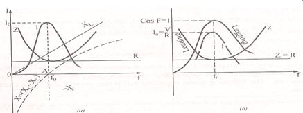
Resistance : it is independent of f, hence it is represented by a straight line
Inductive Reactance: it is given by XL = 2πfL. This increases linearly with frequency. Hence its graph is a straight line passing through origin.
Capacitive reactance: XC = 1 / 2πfC. It is inversely proportional to frequency. Its graph is a rectangular hyperbola which is drawn in the fourth quadrant (as XC is considered negative.
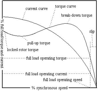
30.
Sketch a graph of starting current and torque against the speed of
rotation for a single cage motor?
Torque
curves for 4 types of asynchronous induction motors:
A) Single-phase motor
B) Polyphase squirrel cage motor
C) Polyphase squirrel cage bar deep motor
D) Polyphase double squirrel cage motor
typical
torque curves for different line frequencies
typical
torque curve as a function of slip
the
left side indicates when RPM is more than synchronous speed, the motor behaving
like an induction generator. The right
side is the normal graph
31.
Compare the effectiveness of a current limiting circuit breaker with
that of a HRC fuses?
Many electrical distribution systems can deliver large short circuit currents to electrical equipment. This high current can cause extensive damage. Current limiting circuit breakers will reduce the current flowing in the faulted circuit to substantially less magnitude. This helps protect expensive equipment. One way to accomplish current limiting is with an additional set of contacts that feature two moveable arms. These are referred to as dual-pivot contacts, which separate even more quickly than the single-pivot contacts. The dual-pivot contacts are connected in series with the single-pivot contacts. As with the single-pivot design, current flows in opposite directions through the contact
arms, creating a magnetic repulsion. As current increases, the magnetic repulsion force increases.
In an overload condition where current may only be one to six times normal current, the contacts remain closed until the breaker trips. In a short circuit condition fault current is extremely high, both sets of contact arms may open simultaneously, generating high impedance arcs. The contact
gap of the dual-pivot contacts increases more rapidly, therefore generating arc impedance more rapidly. Once the arcs are extinguished, the dual-pivot contacts close on their own due to spring tension. The single-pivot contacts are held open by the breaker mechanism, which will have tripped during the fault and must be manually reset.
{a current limiting circuit breaker as ‘one that does not employ a fusible element and, when
operating within its current-limiting range, limits the let-through I2t to a value less than the I2t of a 1/2-cycle wave of the symmetrical prospective current.’ Furthermore, I2t is defined as ‘an expression related to the circuit energy as a result of current flow. With respect to circuit breakers, the I 2t is expressed for the current flow between the initiation of the fault current and the clearing of the circuit.’ Expressed graphically, the energy in the circuit, I2t, is represented as the area under the curve.}
32.
Derive an expression for the emf induced in an ac generator?
Let Z = number of conductors / phase
2T where T is the number of coils or turns per phase.
P = number of poles
f = frequency of induced emf in Hz
φ = flux/pole in webers
N = rotor rpm
Kd = distribution factor of the winding
Kc = pitch or coil span factor
Average induced emf per conductor = dφ / dt ; dφ = φP
dt = 60 / N sec
hence, average induced emf per conductor = φP / 60/N = φPN/60
but f = PN / 120, hence N = 120 f / P;
average induced emf/conductor = φP x 120 f / P x 60 = 2 f φ volts.
Total number of conductors is Z/phase or 2T/phase,
Hence induced emf/phase = 2 f φ x 2T = 4 f φ t volts.
RMS value of induced emf / phase = 1.11 x 4fφT volts = 4.44 f φ T volts.
This would have been the actual value of the induced voltage if all the coils in a phase were full pitched and concentrated or bunched in one slot (instead of being distributed in several slots under poles). This not being so, the actually available voltage is reduced in the ratio of the winding factors.
Hence actual voltage available per phase = 4.44 kpkdfφT volts.
33. How do the leakage fluxes effect the operation of a transformer and how are they minimised?
Answered in question No. 27
34. What is the operational impedance of an RC circuit, describe its usefulness?
Capacitors oppose changes to a circuit’s voltage
• Inductors oppose changes to a circuit’s current
• These components will offer resistance to current flow, and the amount of resistance changes as
the circuit’s operating frequency changes. This opposition to alternating current is called impedance.
• AC circuits will have time delays due the component’s opposition to change.
The inductive reactance is represented as XL and the capacitive reactance is represented as XC.
The operational impedance
Z = √ R2 + (XL - XC)2
If XL is greater than XC., then circuit behaves like an inductive circuit and if XC. Is greater than XL then circuit behaves like a capacitive circuit.
The impedance effect as inductive circuit are useful as current limiting reactors in the main switch board, as better storage medium where as the capacitive circuit is utilised for power factor improvement and voltage improvement. The other uses are in electronic circuits like Phase Shift circuits, A Voltage Divider, RC Low Pass Filter etc.
35.
What is back emf. Derive the relation for the back emf and supplied
voltage in terms of armature resistance?
When the armature of a d.c. motor rotates under the
influence of the driving torque, the armature conductors move through the
magnetic field and hence e.m.f. is induced in them as in a generator The
induced e.m.f. acts in opposite direction to the applied voltage V(Lenz’s law)
and in known as back or counter e.m.f. Eb. The back e.m.f. Eb (= P Φ ZN/60
A) is always less than the applied voltage V, although this difference is small
when the motor is running under normal conditions.
Consider
a shunt wound motor shown in Fig. When
Net
voltage across armature circuit = V – Eb
If
Ra is the armature
circuit resistance, then, Ia =
(V – Eb)/ Ra
Since
V and Ra are usually
fixed, the value of Eb will
determine the current drawn by the motor. If the speed of the motor is high,
then back e.m.f. Eb (=
P Φ ZN/60 A) is large and hence the motor will draw less armature current
and viceversa.

36.
Describe the materiel used for conductors in cables?
In order to transmit electrical current with as few losses as possible,
a cable conductor needs to be of low resistivity (or high conductivity). There
are two main cable conductor materials used in practice, copper and aluminium,
because of their low resistivity characteristics, coupled with their relatively
low cost. Silver has better resistivity characteristics than either copper and
aluminium, but being a precious metal, is far too costly.
The resistivity of copper is in the
order of 1.7 - 1.8 ![]() Ωmm2 / m.
Copper is a denser material than aluminium and has a higher melting point,
hence has better performance under short circuit conditions and is mechanically
stronger. However the high density of copper makes it less flexible than
aluminium. Copper conductors also need to be very pure, and small traces of
impurities (e.g. phosphorous) can significantly affect conductivity.
Ωmm2 / m.
Copper is a denser material than aluminium and has a higher melting point,
hence has better performance under short circuit conditions and is mechanically
stronger. However the high density of copper makes it less flexible than
aluminium. Copper conductors also need to be very pure, and small traces of
impurities (e.g. phosphorous) can significantly affect conductivity.
Copper is typically used more commonly in industrial plants, generating
stations and portable equipment because of its mechanical properties.
Furthermore, it is used in applications where space restrictions abound, e.g.
offshore platforms and aircraft
The resistivity of aluminium is around
2.8 ![]() Ωmm2 / m,
which makes it roughly 60% less conductive than copper. Therefore, aluminium
conductors need to be oversized by a factor of 1.6 in order to have the
equivalent resistance of copper conductors. However aluminium is also 50%
lighter in mass than copper so it has a weight advantage. Additionally, it is
more malleable and flexible than copper.
Ωmm2 / m,
which makes it roughly 60% less conductive than copper. Therefore, aluminium
conductors need to be oversized by a factor of 1.6 in order to have the
equivalent resistance of copper conductors. However aluminium is also 50%
lighter in mass than copper so it has a weight advantage. Additionally, it is
more malleable and flexible than copper.
Aluminium is inherently corrosion resistant due to the thin oxide layer
that is formed when aluminium is exposed to the air. Aluminium also performs
better than copper in sulfur laden environments (in terms of corrosion
resistance).
Aluminimum is typically used for overhead aerial lines because of its
light weight and high conductivity. It is also used in applications where space
restrictions are not a large factor, e.g. underground cables
|
|
Copper |
Aluminium |
|
Advantages |
High
conductivity High
mechanical strength Good
short circuit performance |
Lower
weight Flexible
and malleable Corrosion
resistant |
|
Disadvantages |
Heavier
and less flexible Impurities
have large effects on conductivity |
Lower
conductivity than copper Low
mechanical strength |
Common materials used in electronic circuits and coaxial
cable systems include copper, tinned or silver plated copper, copper clad steel
and copper clad aluminum. Plated copper is used to aid in solderability of
connectors or to minimize corrosion effects. Because of a phenomena known as
skin-effect, copper clad materials may be used in higher frequency
applications.
37. Describe the effect of changes in speed, rotor current and torque as load is applied to an induction motor. How does the motor adjust its stator current with changes in mechanical load?
When a load is applied to the rotor of an induction motor, the motor speed reduces. Torque increases . If load is going on being increased, then the torque will increase upto the break down torque and after wards the motor torque decreases till pull out torque condition (if loading continues) and motor stops subsequently. This reduction in speed on load would cause the induced current and voltage in the rotor to increase, as well as the magnetic field in the rotor conductors. This also causes an increase in slip. The back emf which normally opposes the terminal voltage will decrease proportionately, hence the stator current will increase.
The action of this transfer to stator is like a transformer action. Stator can be considered as primary and the rotor as secondaty. When rotor is loaded, it corresponds to the secondary of a transformer getting loaded, hence by mutual induction, the primary or stator current increases.
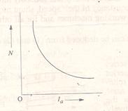
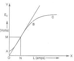
38. Describe the no load saturation characteristics of a dc generator?
It is a curve drawn by taking no load generator emf E0 on Y axis and the field current If on X axis as shown in figure. It is clear that the curve is not starting from zero. It is due to the residual magnetism present in the poles. Thus even if If = 0, there is some voltage ‘OA” due to the residual flux. The portion AB is practically a straight line. It is due to the fact that a t low flux densities, the reluctance offered by iron path is negligible. Hence the total reluctance is only due to air gap which is constant. Thus as If increases E0 also increases. The portion BC refers to saturation, i.e at higher flux densities iron path reluctance becomes appreciable and hence E0 will no more be proportional to If.