Question
Sketch a main engine shaft driven generator with electronic
system for frequency correction
Describe the operation of the generator arrangement
sketched.
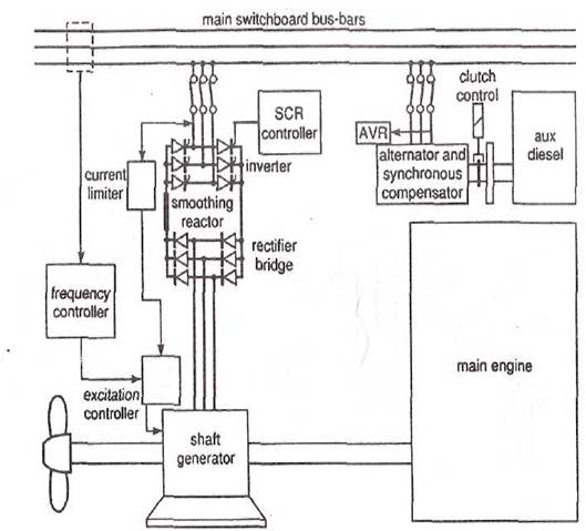
Figure. Shaft
generator system with static frequency converter.
The converter system
shown (Figure) serves the shaft generator of a ship with a fixed-pitch
propeller and a large main-engine speed range.
The shaft generator must
supply full output over the permitted speed range, and to achieve this at the
lower end (i.e. down to 40% of the rated speed), it is overrated for higher
speeds.
The a.c.
shaft generator itself is a synchronous machine which produces alternating
current with a frequency that is dictated by variations in engine speed.
At the full rated r.p.m., frequency may match that of the electrical system.
The output is delivered
to the static converter, which has two main parts.
The first is a rectifier
bridge to change shaft generator output from alternating to direct current.
The second part is an
inverter to change the
Alternating current from the shaft generator, when delivered to the
three-phase rectifier bridge, passes through the diodes in the forward
direction only, as a direct current.
The smoothing reactor reduces ripple.
The original frequency (within the limits) is unimportant once the
supply has been altered to
The inverter for
transposition of the temporary direct current back to alternating current is a
bridge made up of six thyristors.
Direct current,
available to the thynstor bridge, is blocked unless the thyristors
are triggered or fired by gate signal.
Gate signals are
controlled to switch each thynstor on in sequence, to
pass a pulse of current.
The pattern of alternate current flow and break constitutes an
approximation to a three-phase alternating current.
Voltage and frequency of the inverter supply to the a.c.
system must be kept constant within limits.
These characteristics are controlled for a normal alternator by the
automatic voltage regulator and the governor of the prime mover, respectively.
They could be controlled for the shaft alternator inverter by a separate
diesel-driven synchronous alternator running in parallel.
The extra alternator could also supply other effects necessary to the
proper functioning of an inverter, but the objective of gaining fuel and
maintenance economy with a shaft alternator would be lost.
Fortunately the benefits can be obtained from a synchronous compensator
(sometimes termed a synchronous condenser), which does not require a prime
mover or driving motor except for starting.
The compensator may be an exclusive device with its own starter motor or
it may be an ordinary alternator with a clutch on the drive shaft from the
prime mover.
The a.c.
generator set that fulfils the role of synchronous compensator for the system
shown (Figure) is at the top right of the sketch.
The diesel prime mover
for the compensator is started and used to bring it up to speed for connection
to the switchboard.
The excitation is then set to provide the reactive power, and finally
the clutch is opened, the diesel shut down and the synchronous machine then
continues to rotate independently like a synchronous motor, at a speed
corresponding to the frequency of the a.c. system.
A synchronous compensator is used with the monitoring and controlling
system, to dictate or define the frequency.
It also maintains constant a.c. system
voltage, damps any harmonics and meets the reactive power requirements of the
system and converter, as well as supplying, in the event of a short circuit,
the current necessary to operate trips.
The cooling arrangements
for static frequency converters include the provision of fans as well as the
necessary heat sinks for thyristors.