Question
With reference to a 3speed a.c. cage motor driven
cargo winch
Sketch a circuit diagram for a pole change motor
Describe how speed change and braking are achieved
Answer.
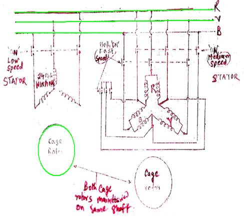
Three speed pole changing winch motor employ dual motors in
which one cage rotor operating in a stator wound for say 24 poles gives a low
speed where as other cage rotor operating in a pole amplitude modulated stator
wound for say 8 poles to give medium speed and 4 pole to give high speed
The low speed 24 pole stator winding has a single winding per
phase and for low speed operation the stator contactor closes and provides
power supply to the winding when all the contactors are kept open
For medium and high speed operation the pole amplitude
modulated stator has two windings in each phase with a centre lap. One stator
contactor gives supply such that phase winding are in service and 3phase
winding are in delta which makes 8poles and medium speed operation
For high speed operation another two contactor comes ‘ON’,
such that phase winding are in parallel and 8phase windings are in star, which
makes 4poles.
For reversing operation two phase winding are interchanged by
other contactors.
Braking of winch motor
For a 3 phase , 50 Hz supply the
speed of induction motor at 4pole would be about 1400RPM, at 8poles 700RPM, and
24 pole about 200 RPM.
First step slow speed is used for breaking out and decking
second step medium speed is used for handling heavy loads and third step high
peed for normal loads
The lowering speed are slightly higher than those for lifting
as the speed of an induction motor rises slightly when changing over from
motoring to regeneration
For braking winch motor disc operated electromagnetic brakes
are employed. The disc brake is D.C. operated through srlenium
cell rectifiers and is provided with a hand release so that loads may be
released under control in case of a power failure
An independent foot pedal operated brake is also provided
When switching back to the ‘OFF’ position the 24 pole step is
brought in before the brake is applied so that when braking heavy loads the
wear on the magnetic brake is reduced to a minimum
However for luffing and slewing
operation sometimes dynamic braking is employed before magnetic brakes are used
In dynamic braking D.C. supply is injected into the stator
winding just prior to switching off
This has the effect of producing a static field in the stator
Rotation of the stator induces an emf
in the rotor winding and the interaction of the stator field and rotor current
produces torque which opposes the rotating braking power being dissipated in
the form of heat in the rotor winding and in stator from losses
The effectiveness of the method can be adjusted to the
requirement of the carne by adjusting the D.C. voltage
When the crane comes to rest the magnetic brakes are applied
and the D.C. fed to the motor is switched off.