Question
Sketch and describe an
arrangement for automatic connection of emergency batteries upon loss of main
power.
Include in your answer:
Means of obtaining
A method of maintaining charge on
lead acid batteries;
The arrangement to check that
batteries operate at loss of main power
The length of
time for which emergency batteries of passenger and cargo ships must provide
power.
ANSWER
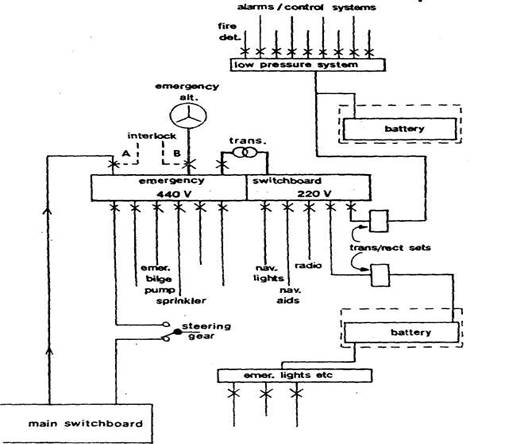
Figure Emergency power supply
Standby emergency batteries
Emergency power or temporary
emergency power can be provided by automatic connection of a battery at loss of
main power. A simple arrangement is shown (Figure) for lead-acid batteries.
This type of secondary cell loses charge gradually over a period of time. Rate
of loss is kept to a minimum by maintaining the cells in a clean and dry state,
but it is necessary to make up the loss of charge: the system shown has a
trickle charge.
In normal circumstances the
batteries are on standby with load switches (L) open and charging switches (C)
closed. This position of the switches is held by the electromagnetic coil
against pressure of the spring. Loss of main power has the effect of
de-energising the coil so that the switches are changed by spring pressure
moving the operating rod. The batteries are disconnected from the mains as
switch C opens, and connected to the emergency load by closing of L.
Loss of charge is made up when
the batteries are on standby, through the trickle charge which is adjusted to
supply a continuous constant current. This is set so that it only compensates
for losses which are not the result of external load. The current value (50 to
100 milliamperes per 100 ampere hours of battery
capacity) is arrived at by checking with a trial value
that the battery is neither losing charge (hydrometer test) nor being
overcharged (gassing).
When batteries have been
discharged on load the trickle current, set only to make up leakage, is
insufficient to recharge them. Full charge is restored by switching in the
quick charge batteries are put back on trickle charge.
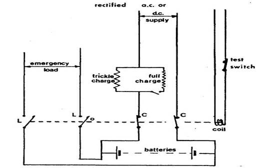
Figure Emergency battery circuit
Charging from a.c.
mains
Mains a.c.
voltage is reduced by transformer to a suitable value and then rectified to
give a direct current for charging. The supply current may be taken from the
230 volt section and changed to say 30 volts for charging 24 volt batteries.
Various transformer/rectifier circuits are used and any of these could be used
(i.e. a single diode and half-wave rectification, two or four diodes and
full-wave rectification, or a three-phase six diode circuit). Smoothing is not
essential for battery charging but would be incorporated for power supplies to
low-pressure
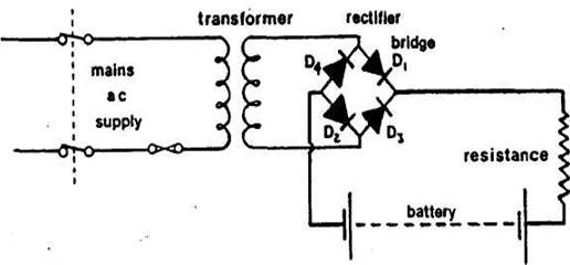
Figure
The circuit shown (Figure ) has a transformer and bridge of four diodes with a
resistance to limit current. The resistance is built into the transformer
secondary by many manufacturers. Voltage is dropped in the transformer and then
applied to the diodes which act as electrical non-return valves. Each clockwise
wave of current will travel to the batteries through D, and return through D2
(being blocked by the other diodes). Each anti-clockwise wave will pass through
D3 and back through D4. Thus only current in one direction will reach the
batteries.
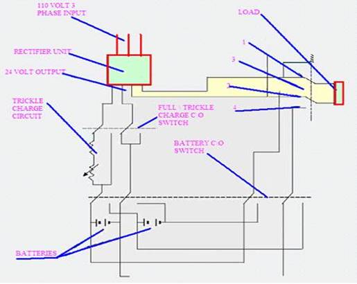
The circuit sketched shows a
standby battery system which is used as a back up system in the event of total
power failure, so that power is maintained to important sources such as alarm
panels, communications etc.
In the event of power failure, a
two-pole switch which is held on contacts 1 and 2 by an energiesd
Coil in normal operating condition i.e. from the mains supply will change over
due to loss of Power onto contacts 3 and 4, now power is supplied from
the back up batteries.
The battery change over switch is
normally changed over weekly to ensure both sets of batteries Are fully charged. The batteries off load being charged,
while the batteries that are not, are on Stand-by for
loss of power.
Passenger vessels
If the batteries are the only
source of power they must supply the emergency load without recharging or excessive
voltage drop (12% limit) for the required length of
time. Because the specified period is up to 36 hours, batteries are used
normally as a temporary power source with the emergency generator taking over
essential supplies when it starts.
Batteries are fitted to provide
temporary or transitional power supply, emergency lights, navigation
lights, watertight door circuits including alarms and indicators, and internal
communication systems. In addition they could supply fire detection and alarm
installations, manual fire alarms, fire door release gear, internal signals,
ship's whistle and daylight signalling lamp. But some of these will have their
own power or take it from a low-pressure
Cargo vessels
Emergency power for cargo ships
is provided by accumulator battery or generator.
Power available for emergencies
must be sufficient to operate certain essential services simultaneously for up
to 18 hours. These are: emergency lights, navigation lights, internal
communication equipment, daylight signalling lamp, ship's whistle, fire
detection and alarm installations, manual fire alarms, other internal emergency
signals, the emergency fire pump, steering gear, navigation aids and other
equipment. Some essential services have their own power or are supplied from a
low-pressure
Transitional batteries are
required to supply for 30 minutes power for emergency lighting, general alarm,
fire detection and alarm system, communication
equipment and navigation lights.