Question
With
reference to electronic control systems:
(a)
Draw a simple block diagram for temperature control;
(b)
Describe each component shown in the diagram in (a).
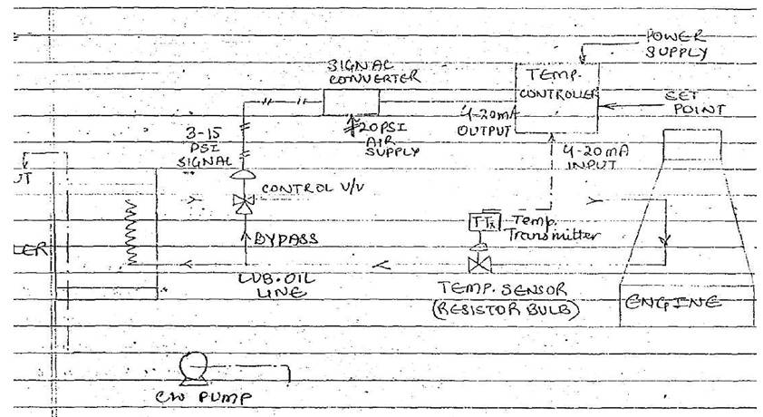
Control scheme
The hot oil coming out of the engine is sent to a cooler
where cooling water is continuously circulated by a pump.
The cooler outlet oil line has a 3 way valve [pneumatic
control] for manipulating the quantity of oil through the cooler.
The control valve outlet line is connected to the engine oil
inlet port. A temperature sensor, usually a RTD [resistance temperature
detector] is fitted on the engine oil outlet line to measure temperature
The RTD gives a change of resistance output proportional to
temperature.
This signal is converted into a standard 4-20mA current
signal in the transmitter and fed to the controller
The controller compares the signal with the set point
and based on the error (measured temperature set point) gives an output of
4-20mA range
The current output is converted into corresponding 3-15PSI
pneumatic signal in the signal convertor and fed to the control valve so as to
regulate the oil flow through the cooler. The 3 way control valve is used so
that if sensed temperature is higher, most of the oil will go via bypass and
minimum will flow through the cooler.
The Instrument Component Used In The Scheme are explained as follows
Temperature
sensor.
An RTD is used to detect
temperature
This is made up of a coil of
platinum wire over mica strip and encapsulated in ceramic or SS enclosure for
mechanical rigidity
The resistance of this coil changes
with temperature in linear relation
The change in resistance is
indicative of temperature.
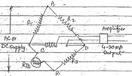
Temperature transmitter
The RTD change in resistance can be
detected by a Wheatstone bridge circuit and a corresponding output current of
4-20mA is generated in the transmitter
The Wheatstone bridge circuit
consist of 4 arms as shown
Across A & B, the bridge supply
is given R1, R2, And R3. is
chosen based on instrument calibration range and RTD is connected to 1 arm
Across C & D the current changes as RTD resistance changes.
This is amplified and adjusted to
4-20mA corresponding to temperature change.
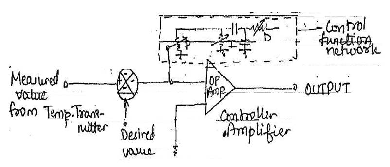
Controller.
The electronic controller can be an
on / off or continuous controller using P+I+D logic. It has a main power and
receives 4-20mA input from transmitter. The desired value of temperature is set
as set point in it.
The controller compares the actual
value and the set point and based on error [difference between actual and set]
generates an output [4-20mA] depending on the P,I,D.
SETTING
The Out Put Generated In The
Controller Will Be In Such A Direction [ Increasing
Signal Or Decreasing Signal] So As To Move The Control Valve To A Position Of
Balance, i.e. The Oil flow through cooler and bypass manipulated to make the
measured temperature equal to set point
In other words the controller keeps
acting till the error becomes zero.
Signal converter.
For ease of use and maintenance a pneumatic
control valve is generally preferred. It requires a control signal of 3-15PSI
air signal
Since electronic controller gives a
4-20ma current output, a signal converter is used to change this into a
proportional 3-15PSI air signal. The signal converter uses the principle of
mutual induction in creating movement of core when current through the coil on
it changes
The physical movement is
mechanically linked to a flapper / nozzle mechanism to generate 3-15Psi pneumatic
signal, hence 4-20mA current signal gets converted to
3-15PSI air signal.
Control valve. The pneumatic
control valve is a 3way valve. The main parts connected between cooler and
engine inlet while the bottom part is a bypass passage between cooler inlet and
outlet. The control air signal [3-15PSI ] acts on a
diaphragm against a calibrated spring and causes linear movement proportional
to signal. The stem carries the plugs that move against the seat rings varying the
opening of ports
At extreme positions only one port
is open, the other closed. The control signal manipulates the relative opening
of he two ports. The valve can be fitted with a valve positioner
to enhance speed of operation and better stability of stem. Valve positioner will need a separate setting of air supply that
can be given through an air regulator.