Question
With reference to squirrel cage, induction,
electric motors:
(a) Describe the construction of such a motor;
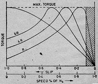
(b) Sketch
the torque against speed curve of such a motor.
(c) Describe a method employed by a retro-fitted
device used to improve the part load performance of an induction motor.
The stator of an induction motor is,
in principle, the same as that of a synchronous motor or generator. it is made up of a
number of stampings which are slotted to receive the windings.
The stator carries a 3-phase winding and is fed from a
3-phase supply, it is wound for a definite number of
poles, the exact number of poles being determined by the requirements of speed.
Greater the number of poles, lesser
the speed and vice versa.
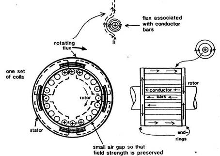
The stator windings, when supplied with 3-phase currents,
produce a magnetic flux which is of constant value but which revolves (or
rotates) at synchronous speed (given by Ns = 120fp). This revolving magnetic
flux induces an e.m.f. in the rotor by mutual
induction. Stator windings of an induction motor can be arranged in various
ways so that a supply of three-phase alternating current will produce a
rotating magnetic field. The method shown in Figure has three sets of coils at different
pitch circles with a 30% overlap.
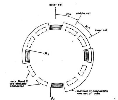
Method of connection
of the coils
The outer set are connected as in Figure so that current flow
between A, and A2 will produce magnetic fields simultaneously in the four coils
but that the polarity of the top and bottom will be the same and opposite to
that of the other two. Current flow follows in coil sets B and C, and then the
sequence is repeated with the direction of current reversed. The effect is to
cause a rotating field.
Almost 90 per cent of induction motors are squirrel-cage
type, because this type of rotor has the simplest and most rugged construction
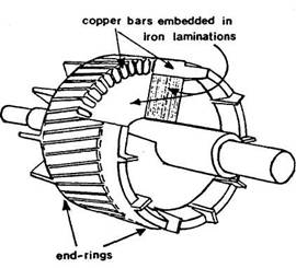
imaginable and is almost indestructible. The rotor consists of a cylindrical
laminated core with parallel
slots for carrying the rotor conductors which, it should be noted
clearly, are not wires but consist of heavy bars of copper, aluminium or
alloys. One bar is placed in each slot, rather (he bars are inserted from the
end when semi-closed slots are used. The rotor bars are brazed or electrically welded or
bolted to two heavy and stout short-circuiting end-rings, thus giving us, what
is so picturesquely called a squirrel-cage construction.
It should be noted that the rotor bars are permanently
short-circuited on themselves, hence it is not
possible to add any external resistance in series with the rotor circuit for
starting purposes.
The rotor slots are usually not quite parallel to the shaft
but arc purposely given a slight skew (Fig. 29-4). This is useful in two ways :
(1) It helps to make the motor run quietly by reducing the
magnetic hum and
(2) It helps in reducing the locking tendency of the rotor
i.e. the tendency of the rotor teeth to remain under the stator teeth due to
direct magnetic attraction between the two.
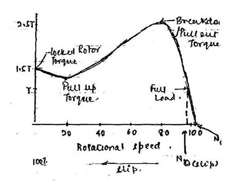
T= Rated
troque.
Starting troque
= 1.5T
Maxi,um troque = 2.5t
T = KφsE2R2 / (R2)2
+ (sX2)2
At 0 slip T = 0
Under normal condition [running] slip is minimum
Factor sX2 is negligible with respect to R2
Therefore T α s / R2
Hence for low values of slip, the torque / slip curve is
approximately a straight line.
As slip increases [for increasing load on the motor] the
torque also increase and becomes maximum where s = R2 / X2
This torque is known as pull out or
break down torque
or stalling torque.
As slip further increases [i.e. motor speed falls] with
further increase in load, then R2 becomes negligible as compared to sX2
therefore for larger values of slip T α s / sX2 α 1/s
Hence, the torque/slip curve is a rectangular hyperbola. So,
we see that beyond the point of maximum torque, any further increase in motor
load results in decrease of torque developed by the motor. The result is that
the motor slows down and eventually stops. The circuit-breakers will be tripped
open if the circuit has been so protected. In fact, the stable operation of
motor lies between the values of s =0 and that corresponding to maximum torque.
The operating range is shown shaded in Fig.
It is seen that although maximum torque does not depend on R2,
yet the exact location of Tmax is dependent on it.
Greater the R2, greater is the value of slip at which the maximum torque
occurs.