Brushless alternator
Self-Excited
Error Operated A.C. Generator
switchboard
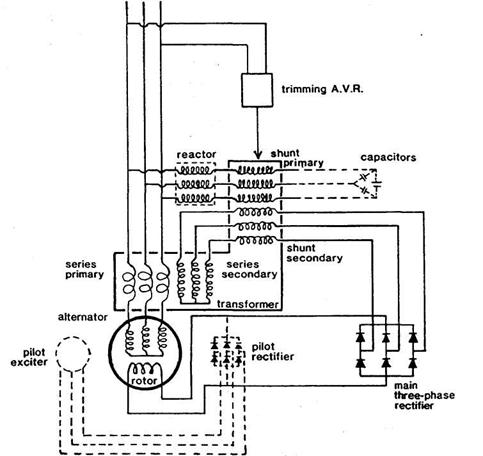
Static excitation system principle
Excitation of
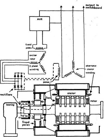
self excited brushless a.c generator
This type of generator is the most common type used on
modern ships.
1. The main rotor has residual magnetism
which produces a weak magnetic field.
2. So when the rotor turns, this weak
field flux cuts the main stator winding.
3. A low voltage is generated in the main
stator.
4. This output is fed back to the AVR
which rectifies the a.c. power to d.c.
5. This
6. A stationary magnetic field is created
in the exciter stator by the
7. The exciter rotor, when it rotates,
cuts this stationery field.
8. Since the exciter rotor windings are
wound to produce 3 phase a.c. power, 3 phase a.c. is generated in it.
9. All of this 3 phase a.c.
is led to a bank of rotating diodes mounted on the same shaft.
10. The diodes convert all of this a.c. to d.c.
11. This d.c is the
“excitation” of the main generator.
12. This
13. So the total field flux produced by the
generator rotor is now increased: field flux due to current feedback from AVR
& field flux due to residual magnetism.
14. Since more flux now cuts the generator
stator windings, a higher voltage is generated.
15. This process of voltage build-up
continues until the generator rated terminal voltage (usually 440V) is
reached. The AVR regulates the voltage
to this value.
b)
Both
the 'conventional' alternator with
The
voltage has to change for the AVR to register the deviation from normal and to then adjust the excitation
for correction.
The
suddenness of the initial volt dip (blamed
specifically on transient reactance) is such that the response from the error-operated system cannot come until
the dip is in the second slower stage.
Thus
neither machine can prevent the rapid and vertical volt dip due to transient
reactance, but the faster acting voltage
regulator of the brushless machine will arrest the voltage drop sooner on the slower secondary part of
its descent.
The
carbon pile regulator is slow compared with the static type but better recovery by the
brushless alternator is also achieved by field forcing, i.e. boosting the excitation to give a
quicker build-up.
AVR will control generator voltage to ± 2.5% [or better] of it’s set value over the load range.
This is the steady state voltage regulation.
Transient voltage dip is usually limited to 15% for a
specified sudden load change with recovery to rated voltage with in 1.5
seconds.
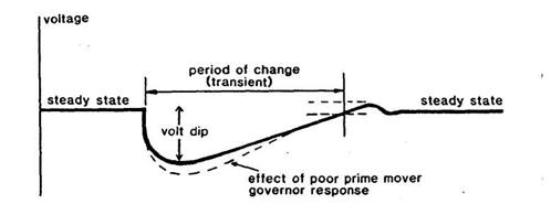
Typical volt dip/recovery pattern for an alternator
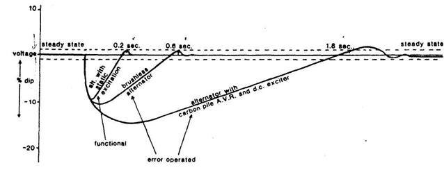
Voltage dip
recovery for brushless alternator [error operated]