Question
How
do the leakage flux effect the operation of a
transformer
How
are they minimised
In the preceding
discussion, it has been assumed that all the flux linked with primary winding
also links the secondary winding. But, in practice, it is impossible to realize
this condition.
It is found,
however, that all the flux linked with primary does not link the secondary but
part of it i.e. ΦL1
completes its magnetic circuit by passing through air rather than around
the core, as shown in Fig
a
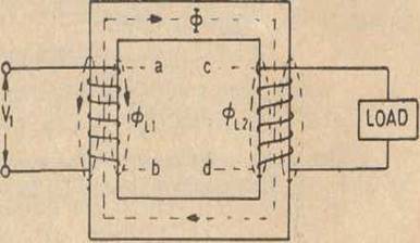
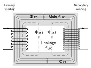
Fig a
This leakage
flux is produced when the m.m.f. due to primary
ampere-turns existing between points a and b,
acts along the leakage paths.
Hence, this flux
is known as primary leakage flux and is proportional to the primary
ampere-turns alone because the secondary turns do not link the magnetic circuit
of ΦL1. The
flux Φl1 is in time phase with /,. It induces an e.m.f. eL1in
primary but none in secondary.
Similarly,
secondary ampere-turns (or m.m.f.) acting across
points c and d set up leakage flux Φl2 which is linked with secondary winding
alone (and not with primary turns).
This flux Φl2 is in time phase with I2 and produces a
self-induced e.m.f. in secondary (but none in
primary).
At
no load and light loads, the primary and secondary ampere-turns are small,
hence leakage fluxes are negligible.
But
when load is increased, both primary and secondary windings carry huge
currents.
Hence,
large m.m.f.s. are set up
which, while acting on leakage paths, increase the leakage flux.
As said earlier,
the leakage flux linking with each winding, produces a
self-induced e.m.f. in that winding.
Hence, in
effect, it is equivalent to a small choker or inductive coil in series with
each winding such that voltage drops in each series coil is equal to that
produced by leakage flux.
In other words, a
transformer with magnetic leakage is equivalent to an ideal transformer
with inductive coils connected in both primary and secondary
circuits as shown in Fig. b
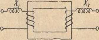
Fig b
Such that the internal e.m.f. in each inductive coil is equal to that due to the
corresponding leakage flux in the actual transformer.
Following
few points should be kept in mind :
(1)
The leakage flux links one or the other winding but not both, hence it in no way contributes to the
transfer of energy from the primary to the secondary winding.
(2)
The primary voltage V1 will have
to supply reactive drop I1X1 in addition to
I1R1 Similarly :-Eb
will have to supply I2R2 and I2X2.
(3)
In an actual transformer, the primary
and secondary windings are not placed on separate legs or limbs as shown in
Fig. b because due to their being widely separated, large primary and secondary
leakage fluxes would result.
These leakage
fluxes are minimised by sectionalizing and
interleaving the primary and secondary windings as in Fig. b