Question
With reference to the
condition monitoring, of electrical machinery:
(a) State TWO important parameters that may be
recorded;
(b) Explain how the
parameters are measured and what defects may be revealed.
Answer.
Condition Monitoring (another form of preventive maintenance) is that
in which equipment is regularly monitored and tested.
When monitoring indicates
that breakdown is imminent, the equipment is repaired or replaced and any other
specified maintenance procedures carried out
Regular insulation testing
and vibration testing are two forms of condition monitoring.
Insulation resistance – all
electric equipment has insulation. The purpose is to keep electric current in
the conductor and to prevent contact with live wires. The electrical resistance
of insulation must be very high [mΩ] to prevent
current leaking away from conductor. Insulation resistance is measured between
Conductor and earth,
Conductors.
The electrical insulation
of electrical machines and cables is regularly measured using a standard 'Megger' type insulation tester.
Vibration
measurement
All machinery installations
have characteristic vibrations when in operation. Recordings of these vibration
characteristics, taken when the machinery is in good condition and operating
satisfactorily, provide a standard against which to judge the future condition
of the machinery, to diagnose faults and to decide on the maintenance required.
Measurement of insulation resistance.
Preparing for the actual test.
Correctly preparing the
equipment and insulation tester is crucial to your safety and the well being of
your wiring and machinery. Adhere to the following four-step process before
every test:
Take the
equipment out of service.
Shut down the apparatus,
open all switches, and de-energize the unit. Disconnect the equipment under
test from all other equipment and circuits, including neutral and protective
ground connections. Make sure you follow proper lock-out/tag-out procedures
during this step.
Check what will
be included in the test.
The more equipment included
in a test, the lower the resistance reading. For this reason, it's very
important to inspect the installation and understand exactly what you're
including in the test. You don't want a true reading to be affected by
additional equipment. However, if a complete installation with several pieces
of equipment yields a high reading, it's safe to assume that each individual
apparatus will yield an even higher reading. Consequently, sometimes separating
components is unnecessary.
Discharge
capacitance.
It's important to discharge
capacitance before and after making an insulation resistance test. You should
discharge about four times as long as the test voltage was applied during the
test.
Check current
leakage at switches.
Make sure readings won't be
affected by leakage over and through switches, fuse boxes, or other
connections. Such leakage can be detected by watching the level of resistance
the moment the test leads are attached. Never perform an insulation test on an
energized line or apparatus.
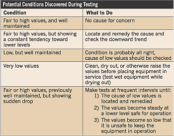 Interpreting test results.
Deciding what to do with
the results of an insulation test can often be more complicated than actually
conducting the test itself. Every piece of equipment has a general insulation
“personality.” In other words, no two pieces of equipment may operate exactly
the same, but if a machine is behaving in accordance with its normal
tendencies, there's usually no cause for concern. However, a safe rule of thumb
is to judge results against a 1 megohm per 1,000V
ratio. Use the information shown in Table 2 on page 46 as a guideline for what
to do with the various conditions you may discover during your testing.
It's extremely important
that you consult the motor manufacturer's operating handbook for specific
information and guidance as to whether a particular value measured between two
points should be considered acceptable or questionable.
Insulation testing
manufacturers can provide test equipment capable of providing you with accurate
readings, but they have no way to determine if a particular measured value
indicates that a piece of equipment meets its specifications for insulation
integrity.
Continuity testing procedure.
Devices that can be used to
perform continuity tests include multimeter which
measure current
The following safety
precautions are the MINIMUM for using a multimeter.
· De-energize and discharge
the circuit completely before connecting or disconnecting a multimeter.
· Never apply power to the
circuit while measuring resistance with a multimeter.
· Connect the multimeter in series with the circuit for current measurements, and in parallel for voltage measurements.
· Be certain the multimeter is switched to ac before attempting to measure
ac circuits.
· Observe proper dc
polarity when measuring dc.
· When you are finished
with a multimeter, switch it to the OFF position, if
available. If there is no OFF position, switch the multimeter
to the highest ac voltage position.
· Always start with the highest
voltage or current range.
· Select a final range that
allows a reading near the middle of the scale.
· Adjust the "0
ohms" reading after changing resistance ranges and before making a
resistance measurement.
· Be certain to read ac
measurements on the ac scale of a multimeter.
· Observe the general
safety precautions for electrical and electronic devices.
In case of 3phase motor and
transformer all reading should be identical
If one reading is smaller
than the other this could indicate the possibility of short circuit turns in
that winding
Conversely a high
continuity resistance value indicates a high resistance fault or an open
circuit.