

Question
The figure shows an electrical circuit
used to measure the temperature of a gas. When the resistance R Is heated by the gas to a certain temperature, a current of
100 mA is observed to flow through the galvanometer
G.

Determine the temperature of R If the
circuit was originally balanced at 30° C
The temperature coefficient of resistance
ft Is 0.0035 per° C.


Question
Determine the magnitude and direction of
the current in the 60Ω resistor shown connected between Band D.


Question

In the circuit the batteries P and Q are
made up of lead acid cells, each having an e.m.f. of
2V and an Internal resistance of 0,001Ω . Battery
P has 60 cells and battery Q has 50 cells.
Calculate the current flowing In each battery and In resistor R.


Question
A two-wire distributor system is fed 440V
at end X and at 425V at end Y, the distance XY being 1650m. Two loads of 110A
and 7OA are supplied from points, 300m and 900m respectively from end X. The
resistance of the cable is 0.33Ω per 1000m.
Calculate the current flowing in each
section of the distributor network and determine the potential difference
across each load.


Question
A vessel has a
Sketch a diagram of the ma in and indicate
there on the amount and direction of the current in each section if the
resistance of the cable is 0.01Ω/1000m.


Question
A battery has an e.m.f.
of 6V and an internal resistance of O.5Ω.
Determine, graphically or otherwise, the greatest power which this battery
can deliver to a load resistor and estimate the value of external circuit
resistance at which this delivery of maximum power will occur.


Question
The voltmeter of internal resistance 8Ω, shown in the figure, reads 6V with
the switch open aid 12V with the switch closed. Neglecting the internal
resistance of the batteries, determine the following:
a)
the current that would flow in a short circuit
between x and Y,
b)
the value of resistance R3,
c)
the value of resistance R2,


Question
Two generators supply loads X and V as
shown in the figure.
Determine:
a)
the current distribution In the system, and
b)
the potential difference across each of the two
loads.


Question
A d,c,
generator of emf. 113V and internal resistance 0.1Ω
is connected to a parallel circuit consisting
of an 11 Ω resistor in one branch and a battery in the
other branch. The battery has 50 cells, each of 2V e.m.f,
and 0.01 Ω internal resistances.
Determine the current flowing In each branch of the
parallel circuit when:
a)
the generator and the battery voltages are in
opposition,
b)
the generator and the battery voltages are not
in opposition.


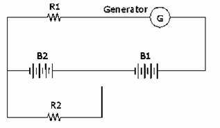
Question
The circuit shown In the figure is used to
charge two batteries B1 and B2 with different values of charging current, B1 consists
of 50 cells, each with e.m.f. 2.2V and internal
resistance 0.12 Ω and
B2 consists of 40 cells each of e.m.f. 1.8V and
internal resistance of 0.10 Ω . The generator has an open circuit e.m.f. of
220V and an armature resistance of 0.2
Ω, The resistors R1 and R2 have values of
3.8 Ω and 80 Ω respectively.
Determine the magnitude of the current
charging each battery


Question
In the circuit shown, determine:
a)
the p.d, between
points X and Y stating clearly which is at the lower potential
b)
power dissipated In each of the 1 Ω
resistor
c)
the energy In watts-hr and In joules supplied
to the circuit in a period of 20 minutes.


Question
A magnetic circuit is built up or
rectangular laminated iron plates of width
The combined depth of the plates Is
Determine the magnetomotive
force required to produce a flux of 0.005 Wb across
the air gap, given that the leakage factor is 1,1, the
relative permeability of iron is 2500, and the permeability of free space Is 4π
x 10 -7 H / m.


Question
A magnetic circuit Is
to be constructed to satisfy the following:
Air gap length 0-
Flux set up in air gap 0,01
Wb
Flux density in air gap 1Tesla
Relative permeability of steel core at
working density 1200
No. of exciting coil turns 300
Supply current
Assuming no leakage or fringing occurs, determine the length of the steel portion of the
circuit to satisfy the above requirements, given that permeability of air is 4π x10-7 H/m
Question
A coil of 1500 turns Is uniformly wound on
an iron ring having a mean diameter of
a)
The relative permeability of the iron If a current of
b)
The current required to maintain the same flux density if an air gap of
length


Question
An iron ring has internal and external
diameters of
Flux density (Tesla) : 1.2 1.3 1.4 1,5
Relative permeability : 2000 1560 1150 750
Determine:
a)
The current required to set up a flux of 200 μ
Wb,
b)
The current required to maintain the same flux of 200μ Wb, and the
corresponding reluctance of the magnetic circuit; if a radial gap


Question
The magnetic circuit shown in the figure Is the arrangement for the overload trip of a starter, The
gaps are set for 25 per cent overload current. If the armature lifts when the
flux density in the air gap is 0,8 Tesla and the
relative permeability of the steel of the magnetic circuit is 2140 at this flux
density, determine the full-load current to the motor for which the starter is
designed. Neglect leakage and fringing. The cross-section of the magnetic
circuit can be taken as being uniform throughout and the permeability of air taken
as 4π x10-7H /m.


Question
A wooden ring has a mean diameter of
a)
the average value of the e.m.f.
Induced in coil B as a result of the current reversal, and
b)
the value of the mutual Inductance between the two
coils.


Question
The ferromagnetic part of a magnetic
circuit shown has a mean length of
The exciting coil is wound with wire of resistivity 0,018 μΩm
and cross-sectional area 0.5 x 10-
Neglecting fringing, determine the direct
voltage which must be applied to the coil in order that a magnetic flux of 1.2 mWb is obtained in the air gap. Given μo
= 4π x10-7
H/m.


Question
A current of
If an identical coil is so arranged that
60 per cent of the flux from the first coil links the second coil, determine
their mutual inductance.
If both coils are arranged in series, with
a current of
a) the mutual fields are
additive, and
b)
the mutual fields are In opposition.


Question
(a)
Explain what is meant by the mutual induction of a pair of coils and
define the unit in which It Is expressed,
(b)
A ring of non-magnetic material having a mean diameter of
Assuming that all the magnetic flux
produced by the current In the first coil links with
the second coil, determine the mutual inductance.
The permeability of free space, μo
= 4π x10-7 H/m


Question
A 3300 / 400 V, single phase transformer
has 300 turns on the primary winding. Determine the magnitude of the maximum
magnetic flux in the coil under normal operating conditions.
If the frequency Is
Increased from 50 Hz to 60 Hz, determine the magnitude of
the primary applied voltage to maintain the maximum flux density In the core
at its previous value,

Question
A single phase transformer with a rated
output of 175 KVA at 2 KV and
operating at 60 Hz has a primary winding of 1000 turns and a secondary winding of
200 turns. Neglecting the magnetizing current and ignoring the winding volt
drops resulting from the winding resistances and leakage reactance’s,
determine:
a)
the magnitude of the primary voltage
b)
the magnitude of the primary current
corresponding to the rated output, and
c)
the peak value of the magnetic flux in the
core.


Question
A single phase transformer has 200 primary
and 480 secondary turns. The effective cross-sectional area of the core is 40 x
10-
a)
the secondary voltage, and
b)
the maximum value of the magnetic flux density
in the core.
Determine the efficiency of the
transformer given that the primary and secondary currents are

Question
A transformer has an efficiency of 97.5
per cent at unity power factor when its load is 3 KVA, the copper and
iron losses being equal at this load, Estimate its efficiency for a performance
over 24 hours if it has no load for 7 hours, quarter load for 5 hours, half
load for B hours and full load for 4 hours.
The Iron loss and power factor may be
assumed to remain constant throughout the period of 24 hours.


Question
A 440 V / 110 V transformer with an
effective primary resistance of 0.5Ω
and a secondary resistance of 0.03Ω
has an Iron loss of 200 W on normal Input voltage. Given that maximum
efficiency occurs when the copper loss Is equal to the
Iron loss, determine:
a)
the secondary current when maximum efficiency
occurs, and
b)
the value of the maximum efficiency on a unity power
factor load.


Question
The primary and secondary windings of a
500 KVA transformer have resistance of0.42Ω
and0.011Ω; respectively. The primary
and secondary voltages are 6600 V and 400 V respectively and the iron loss is 2,9 KW, Determine the efficiency on:
a)
full load, and
b)
half load, assuming the power factor of the
load to be 0.8.


Question
The voltage output from an unstabilized power supply can vary between 20V and 30V.
This is to be used with a resistor and a zener diode,
as shown in the figure, to provide a stabilized voltage output from which
currents of up to 50mA will be drawn. The zener diode
has a "breakdown" voltage of iov
and should be used with a current flowing through it of at feast 1mA;
the resistance of the diode to voltages In excess of 10V Is
8Ω. Determine:
a)
a suitable value of the resistance R when E Is
at Its lowest value and the current to the load Is at its greatest value, and
b)
the stabilized voltage output under these
conditions.


Question
The figure shows a voltage stabilizing
circuit. The breakdown voltage of the voltage referents of the zener diode in this circuit is 8V, and above this voltage
its slope resistance is 15Ω IL isthe current drawn from the circuit.
Determine:
I)
the value of V when E = 10V and IL = 0 mA
II)
the value of V when E = 50V and IL =40mA
iii) the minimum
value of E which will give a stabilized voltage output, v, when
IL = 40 mA,
and
iv) the power
dissipation In the diode and in the resistor when E = 50V, and IL = 20
mA.


Question
The figure shows a circuit diagram with a
bridge rectifier from which the diodes have been omitted.
a)
Reproduce the diagram with the diodes correctly connected to give the
polarity of the output voltage as shown.
b} Determine the magnitude of V,
given that the voltage drop across each diode when conducting is 0.75V,
c)
Estimate the peak value of the ripple voltage If
a constant current of 0.5A Is taken from the rectifier output.


Question
A 230V, SOHz
supply is to be transformed to 40V, then converted to a D.C. supply by a bridge
rectifier and then smoothed by means of a "reservoir capacitor" of
2500μ F,
Sketch an appropriate circuit diagram and
estimate;
a)
the minimum value required for the "peak
inverse voltage" of the rectifier diodes used In the circuit and
b)
the peak to peak value of the ripple voltage
for the circuit when delivering a small current of 250 mA.


Question
A transistor Is
alternately connected In common-base circuit and common-emitter circuit and the
current amplification factors are found to be α
and β respectively,
Show that:
β = α / 1- α
A transistor Is
connected In common-base configuration and when the collector voltage is
constant, a change of 3.26 mA in the emitter current
produces a change of 3 mA in the collector current.
Determine the current amplification factor
of the transistor when It is connected in common-emitter
configuration.


Question
The following data refers to an n-p-n
transistor: Base current flowing IB
= 20 μ A
|
Collector/Emitter voltage VCE
(V) |
1 |
5 |
9 |
|
Collector Current Ic
(mA) |
2.6 |
2.8 |
3.0 |
a)
Determine the d,c. common
emitter current gain at SV and also at 9V.
b)
Determine the "slope" output resistance of the transistor.
c)
Sketch a circuit diagram to show the position of the instruments, and
the means of varying VCE and Ic , to obtain the above data.


Question
For the circuit shown In
the figure, determine:
a)
the collector current flowing,
b)
the voltage at the emitter, at the base and at the collector of the
transistor All voltages being measured with respect to earth, and
t)
the power dissipated in the transistor.
The voltage between the base and the
emitter of the transistor, when conducting, may be taken as 0.6V. The current
gain of the transistor is very high.


Question
The forward characteristics of a junction
diode are as follows;
|
I (mA) |
0.1 |
0.3 1.0 |
3.0 |
|
V (V) |
1 |
2 3 |
4 |
Estimate::
a)
the
forward
b)
the voltage and current when the forward


Question
The negative terminal of an 16V battery Is connected to the emitter of an n-p-n
transistor and the positive terminal Is connected through a 5KΩ resistor to the transistor collector,
I)
Draw a circuit diagram and determine the value of the base current needed
to make the potential difference between the collector and emitter equal to 3V,
giver that the transistor current gain is 120,
ii)
Determine the magnitude of the base current at
which the voltage between the collector and emitter would dminlsh
almost to zero,


Question
The output characteristics for a
common-emitter connected transistor are set out in the following table:
|
Voltage between collector and
emitter |
3 |
7 |
10 |
|
Collector current (mA) when base current is 30μA |
1.0 |
1.20 |
1.5 |
|
Collector current (mA) when base current Is 60μA |
2,1 |
2.55 |
2.9 |
|
Collector current (mA) when base current Is 90μA |
|
3,88 |
4,4 |
a)
Draw the characteristic curves for this transistor and construct load
lines to show the operation from a 6,5V battery with load resistors of 1000Ω and 1500Ω
respectively.
b)
If a suitable value of base bias current Is 60μA
for an Input signal of ± 30μ A, determine the current amplification
for each load.


Question
The equivalent T-circuit of a transistor
used In the figure, where re =
20Ω, rb
= 500Ω
and rc
= 1.5 MΩ.
The transistor Is used with a load
resistance R = 12 KΩ,
Given that the amplification factor α is 0.98, determine:
a)
the current gain,
b)
the voltage gain,
c} the input resistance Rs


Question
The output voltage from an amplifier is
sinusoidal and its magnitude Is limited to ± 24V. Estimate
the maximum output power that can be obtained from this amplifier given that
the load resistance Is 8Ω
,
If the Input voltage and resistance of the
amplifier are 0.1V r.m.s.
and 1 KΩ respectively, determine the
maximum possible:
a)
voltage amplification factor, and
b)
power gain ratio,


Question
A fluorescent lamp, rated at 100W is
equivalent to a pure resistance of 220Ω The
lamp Is to be operated at the rated value from a 250V, 50Hz supply, by having
an Inductive coil (of negligible resistance) connected in series with the lamp,
Determine the Inductance of the coll.
Sketch the phasor
diagram of the circuit and evaluate the phase angle between the current and the
supply voltage


Question
Two coils, A and B, are connected in turn
across a 150V, 50Hz supply. Coil A takes 12 amperes
from the supply and dissipates 270W. Coil B takes 15 amperes from the supply
and dissipates 1125W. When the two coils are connected in series across the
supply, determine:
a)
the current flowing from the supply,
b)
the power taken from the supply,
c)
the overall power factor, and
d)
the value of a pure capacitor, connected In
series with the two coils, to give an overall power factor of 0,6 lead,


Question
A coil of inductance 0.52 H and resistance
120Ω Is
connected In parallel with a 30μ F
capacitor across a 240V, 50Hz supply.
Calculate the total current and the power
factor.


Question
A copper inductor which has an iron core, takes a current of 2A at a lagging power factor of
0.4, from a 240V, 50Hz supply. After the iron core is completely removed, the
inductor takes a current of 4A at a lagging power factor of 0.8, from a 100V,
50Hz supply.
Estimate the Iron core loss sustained by
the Inductor at 50Hz,


Question
An electric circuit consists of a 15Ω resistance in parallel with a series
combination of resistance R and capacitance C, The circuit is supplied from a
50Hz sinusoidal a.c, source, The current taken from
the supply Is 8A, the current in the 15Ω resistance branch is
Determine the phase angle between the
branch currents and evaluate the magnitudes of R and C.


Question
A capacitor and a resistor In series are connected across a 150V, a.c,
supply. When the frequency is 40Hz the current is 5A and when the frequency Is
50Hz the current Is 6A. Determine the values of the
capacitor and resistor.
If the resistor is connected In parallel
with the capacitor across a 150V, 50Hz a,c.
supply, determine the total current and the power factor


Question
A two-branch parallel circuit is connected
across the terminals of a sinusoidal
a.c. supply. One branch contains a resistance of 4Ω
and an inductive reactance of 8Ω , the power dissipated in the branch
being 800W. The other branch contains two pure circuit elements and the total
power dissipated in the whole circuit is 3.15KW at a leading power factor of
0.9.
a)
Identify the elements in the second branch.
b)
Determine the ohm ic
magnitude of each circuit element in the second branch.
c)
Sketch a phasor diagram for the circuit.


Question
A circuit comprising two branches In parallel takes a current I from a 240V, 50Hz supply. One
branch is a pure capacitor of reactance 60Ω
and the other Is an Inductor of resistance Rand
Inductance L The Inductor can be varied, but Its ratio R/L remains constant at
7 5/1.
If the Inductor is adjusted to make,
a)
I a minimum and
b)
I in phase with the supply voltage
Determine each of these values of I and the corresponding currents In the Inductor.


Question
In the figure, the potential difference
across the 8Ω resistor Is 96V, Determine:
a)
the magnitude of the current drawn from the
b)
the mean value of the power drawn from the
supply,, and
c)
the magnitude of the potential difference
across the parallel combination of three resistors.


Question
A coil of resistance 15Ω and inductance 0.05H is connected in
series with a 100 μF capacitor
across a 240V, 60Hz supply.
Calculate;
a)
the value of the voltage across the coil,
b)
the value of the voltage across the capacitor,
c)
the total power taken from the supply,
d)
the resonant frequency for the circuit and
e)
the voltages across the capacitor and the coil
during resonance


Question
A load of 1.8 KVA at a
leading power factor of 0.6 If In parallel with a load of 1.2 KVA at a lagging
power factor of 0.8. Given that the applied
voltage Is 240V, calculate the line current and the power
factor
Sketch a phasor
diagram for the circuit.


Question
Two motors, A and 6, are supplied with
current from a 120V, 50Hi mains source, Motor A takes 1755 Watts and 0.8 power
factor lagging and motor B takes 933 Watts at 0,707 power factor lagging.
Calculate the following;
a)
the current taken by each motor
b)
the total current and overall power factor, and
c)
the capacitance required to raise the overall
power factor to unity when connected in parallel with the load,


Question
Equal currents flow when two coils X and Y
are tested separately across an alternating supply. Coil X is found to have a
power factor of 0,8 and coil Y a power factor of 0.75.
If coils X and Y are now coupled in series
across the same supply, calculate the overall power factor of the circuit.


Question
An a,c.
electrical installation consists of;
a)
one synchronous motor taking 60 KW at a leading
p.f. of 0.6
b)
one induction motor taking 80 KW at a lagging
power factor of 0.7 5
c) a bad of 60 KW at a
lagging p.f. of 0.8
Calculate the resultant p.f. of the installation and the total KVA. Sketch a phasor diagram showing all the power and KVA components.

Question
A 190 KW load at a lagging power factor of
0,5 Is taken from an11KV, 3-phase supply.
When an additional 166 KW load Is taken
from the same supply, the overall p,f
becomes unity,
Determine:
a)
the line current of the 190 KW load when It Is
connected to the supply alone,
b)
the power factor of the 16S KW load,
c)
the line current of the 166 KW load, and
d)
the line current supplying the combined loads.


Question
An unbalanced 3-phase, 4 wire star
connected load is supplied by a line voltage
of 415V and non-inductive loads of 1 KW, 0.6 KW and 0.8 KW are connected
between the central line, and the red, yellow and blue lines respectively.
Determine:
a)
the magnitude of the current in each line, and
b)
the magnitude of the current In the central
line and Its phase displacement from the current In the red line,

Question
A three-phase, 3300V Industrial load
consists of:
(i) a 59 KW motor of
B4 per cent efficiency and 0.9 power factor lagging,
(II)
a load of 120 KVA at unity power factor,
and
(III)
a load of 160 KW at 0,8 power factor lagging.
Calculate:
a)
the total power
b)
the supply current, and
c)
the overall power factor.
Sketch a phasor
diagram showing all of the power and KVA components,


Question
A 400V, 3-phase balanced load takes 4DA at
a power factor of 0.8 lagging, An over excited
synchronous motor is connected parallel to the load to raise the power factor
of the combination to unity. The mechanical output and mechanical efficiency of
the synchronous motor is 12 KW and 91 per cent respectively.
Determine:
a)
the power factor of the synchronous motor, and
b)
the total power taken from the supply mains.


Question
A three phase system supplies the
following loads:
(I)
30 KW of heating and lighting load at unity power factor, (it) 40 KW of induction motor loading at 0.8 p.f, lagging,
A 37.3 KW synchronous motor, efficiency 80%,
Is to be used to raise the overall power factor to 0.95 lagging.
Determine the power factor at which the
synchronous motor must operate:
a)
when used In conjunction with the loads shown
in (I) and (II), and
b)
when used in conjunction with the induction
motor loading only.


Question
A 240V, single phase, 50Hz, 500W-output
motor has a full load efficiency of
70 per cent and a power factor of 0.6
lagging. If the power factor Is to be increased to 0.9
by means of a capacitor connected in parallel with the motor, determine the
minimum required value of the capacitor,
Estimate also the value of a capacitor
which connected In similar manner would improve the
power factor to unity.


Question
A 220V, 4-pole wave wound, shunt generator
has an armature resistance of 0.1Ω
and a field resistance of 50Ω . Calculate the flux per pole, if the machine has 700
armature conductors, runs at 800 rpm and is supplying a 38 KW load.


Question
A shunt generator Is
to be converted Into a level compound generator by the
addition of a aeries field winding. From a test on the machine with shunt
excitation only, it is found that the shunt current is 4.1A to give 440V on no
load and 5.8A to give the same voltage or full load of 200A.
The shunt winding has 1200 turns per pole.
Find the number of series turns required
per pole.


Question
A 240V, 70KW
the terminal voltage.
Calculate the number of series field turns
to produce:
a)
level compounding and;
b)
6 per cent over compounding.
State and explain any assumptions which
have to be made.


Question
The open-circuit characteristic of a d,c, shunt generator operating at
15 rev/s is as follows:
Generated e.m.f,
(V) 100 210
300 360 400
420 Field Current (A)
0.5 1.0 1,5 2,0
2.5 3.0
Plot the open-circuit characteristic of
the generator for a speed of 20 rev/s and determine,
for this operating speed:
a)
the open-circuit generated e.m.f.
If the shunt field resistance Is 200Ω and
b)
the critical resistance value of the shunt field.
The effects of armature resistance and
brush volt drop may be neglected.

Question
A short shunt compound d,c. generator has a terminal potential difference of
125V on no-load, when driven at rated speed. If the terminal potential difference
is to be 130V when the load-circuit current Is BOA, determine the number of series connected
turns per pole given that:
Armature winding resistance = 0.3Ώ
Shunt field circuit resistance = 125Ώ
Number of turns per pole for shunt
winding = 1100
Total brush - commutator
contact voltage loss = 1V
Series field winding resistance = 0.1 Ώ
Estimated field-weakening effect of
armature-reaction at 80A loading
- 50 ampere-turns per
pole


Question
Two similar
Given the following data, determine the
friction and windage loss of each machine and hence
estimate the efficiency of each machine.
Motor circuit current
Generator current
Generator terminal voltage 155 V
Resistance of each machine armatu re 0,7 Ώ
Resistance of each machine field 0.4Ώ


Question
A 50KW, 250V, 750 rev/mln
long shunt d,c. compound
generator has shunt field, series field and armature resistance of 100Ώ, 0.05Ώ and 0.25Ώ respectively. If the prime mover falls and the machine continues to run
as a motor drawing 50A from the 250V bus bars, estimate the speed of the
machine while running in the motor mode.


Question
Two shunt generators are connected in
parallel. Their external characteristics are rectilinear over their normal
working range. The terminal voltage of one generator falls from 270V on no-load
to 240V when delivering 300A to the busbars, whilst
the terminal voltage of the other generator falls from 260V on no-load to 245V
when delivering 200A to the busbars,
If the machines share a common load of
500A, determine:
a)
the current which each machine delivers
b)
the busbar voltage
c)
the power delivered by each machine,


Question
A 240V
The effect of armature reaction may be
neglected.


Question
Ad,c, machine has an armature resistance of 0,2 Ώ and a field winding resistance of 0.3Ώ.The machine is driven as a series connected motor on a 500V d.c. supply when It takes a current of 79.2A and develops a
torque of
500 Nm.
The machine Is then stopped and a 0.2 Ώ resistor is connected In parallel with
the series field winding from outside the machine and the machine Is again
driven as a motor from the same supply until the torque developed Is 550 Nm,
Determine for the final condition, the power
Input to the machine given that ϕ =
0.08 Ip
, for the operating range where ϕ
is the magnetic flux and If is the field current, producing magnetic flux.


Question
A shunt motor supplied from a 220V d.c. supply takes a armature current of 55A when operating
at 10 rev/s, The armature resistance is 0,2 0 ,
Determine the speed at which the motor
would operate if the magnetic flux is increased by 10 per cent and a 0.1Ώ resistance is connected in series with
the armature given that the torque developed by the motor remains unchanged.

Question
A
Estimate the torque of the prime mover
given that the rotational speed of the generator armature Is 6 rev/s.


Question
A d.c, shunt
wound machine gives a n output of 100KW at 440V when
run as a generator at 20 rev/sec. The resistances of the armature and the shunt
field are 0.05 Ώ
and 200 Ώ respectively.
When the machine Is
run as a motor on a 440V supply, the Input power Is 100KW and the iron and
mechanical losses total 3.24KW. When the machine Is
run as a motor, calculate:
a)
the motor speed,
b)
the output power, and
c)
the motor efficiency.


Question
While running without load, the speed of a
100V d.c. shunt motor Is 1000 rev/min and the
armature current Is 1,2A, The armature circuit resistance Is 1Q aid the field
resistance Is 200 Q ,
Calculate the speed and the efficiency of
the motor if the armature current increased to 30A. The windage
and friction losses are proportional to the armature speed squared.


Question
A shunt motor running at normal speed
takes a current of 2A while en no load from a mains supply of 24QV. The motor
has a field circuit resistance of 240 0 and an armature resistance of 0.4 0 .
a)
Estimate the windage and friction loss of the
machine and assuming this loss and the speed of the machine to be constant,
determine the motor power output and efficiency when the current taken from the
mains by the machine is 41A.
b)
If the motor was driven by a prime mover as a shunt generator at the
same speed as before and the terminal voltage and output current delivered by
the generator were 240V and 40A respectively, determine the efficiency of the
machine when running as a generator.


Question
A
a)
Calculate the value of resistance to be Inserted
into the motor circuit In order to reduce the speed by 20 percent. The magnetic
flux per pole may be assumed directly proportional to the current in the field
winding. It is assumed in this calculation that the resistance
of the field and armature windings are zero.
b)
Determine the value of the power In KW, supplied to the motor at the
reduced speed.
Rotational losses In
the


Question
A4KW, 220V d,c> shunt motor has a full-load efficiency of $5
percent and a full-load speed of 12,5 rev per second. The shunt field current Is 1.6A.
Calculate the full load armature current
and the value of starting resistance required if the armature current at start
is to be limited to 1.3 times full-load
value,
If the first step of the starter is to be
cut out when armature current has fallen to full-load value, determine the
speed of the motor when this step Is cut out. The
armature resistance Is 0,55 ohm,


Question
Two alternators, A and 6, connected In parallel, supply 100 KW at 0.8 p.f.
lagging. Machine A supplies 60 KW at 0,7 p.f. lagging. Calculate for machine B:
a)
the KW output,
b)
the KVA output,
c)
the KVAr output, and
d)
the operating power factor.


Question
A load of 8000 KW at 0.8 power factor
lagging is taken from two alternators running in parallel. The load on one
alternator is 2000 KW at 0.543 power factor lagging. Calculate the power factor
of the second alternator and its KVA output Sketch a phasor
diagram of the system.


Question
Two 3-phase star-connected alternators
share a bad of 210 KW, at power factor 0.75 lagging, In the ratio 2:3, The line
voltage Is 2.2 KV. If the current loading on the first machine (I.e. the number
supplying the least power) Is
a)
the current loading on the second machine, and
b)
the power factor at which each of the machine
is operating.


Question
Two 1100 KVA alternators operating tn parallel with similar power
factors share the following loads equally:
500 KW at unity power factor
Induction motor taking 1000 KW at 0,7 lagging.
Synchronous motor taking
500 KW.
Determine:
a)
the power factor at which the synchronous motor
should operate so that the alternators are not overloaded, and
b)
the KVA loading at which the synchronous motor
should operate to raise the power factor of the combined load to unity.
The maximum loading on each alternator is
1000 KW.


Question
Two Identical 3-phase,
star-con nee ted alternators, X and Y, are connected
In parallel and share a load of 3Q0 kva at
p.f. 0.85 lagging, The line p.d.
Is 2,2 KV. When the power output of machine X Is 90
KW, with a lagging power factor and a line current of
a)
the p.f. at which
each machine operates, and
b)
the current supplied by machine Y.
Voltages and currents may be assumed to
vary slnusoidally with time.


Question
Two 6600 V, 3-phase, star-connected alternators
supply the following loads:
500 KW at unity power factor
1200 KWatO.7B power factor lagging
800 KW at 0.7 power factor lagging
One alternator supplies current of
a)
the power supplied
b)
the power factor
c)
the line current.


Question
A 3-phase, 6-pole, induction motor is
supplied from a 3-pfiase, 50 Hz source and operates at unloaded condition with
4 per cent slip.
Determine:
a)
the synchronous speed
b)
the rotor speed, and
c)
the frequency of the rotor current.
If the motor is now loaded and operates at
a steady speed of 10 rev/s, determine the altered
frequency of the rotor current.


Question
A 6-pole, three-phase, 415 V, 60 Hz, Induction
motor has a slip of 5 per cent and takes a current of
Given that the torque lost due to windage and friction Is 10 Nm and that the Iron and copper
losses are 900 watts, estimate the efficiency and power factor of the machine.


Question
a)
State why "slip" is always present in an induction motor, even
when the
motor is running unloaded,
b)
A 3-phase,.
4-pole Induction motor Is supplied from a 50 Hz supply
and runs unloaded with 4% slip.
Determine:
1)
the synchronous speed, 2) the
rotor speed, 3) the frequency of the
rotor current, 4) the speed of
rotation, in space, of the rotor m.m.f., and 5) the rotor e.m.f./phase
when the motor Is running unloaded with 4% slip, if the rotor e.m,f./phase at standstill Is 150 V.


Question
A 4-pole induction motor has its stator
windings connected in delta, the motor obtaining Its energy from a 415 v, 60
Hz, three-phase supply, The shaft-power Is 10 KW and the power factor, overall
efficiency and slip are 0.9, 0.83 and 0,5 respectively.
Determine:
a)
the rotor speed.
b)
the rotor current frequency,
c)
the current flowing In each phase of the stator windings,
d)
the equivalent per phase resistance and
inductance of the motor, expressed in terms of stator windings.


