Question
Differentiate with the aid of
simple sketches between 2 of the following type of electronic circuit.
Rectifier
circuit. Amplifier circuit. Oscillate
circuit.
Half-wave rectification
Figure shows a transformed a.c. supply connected to a load with a rectifier (or
electrical non-return valve) in the circuit.
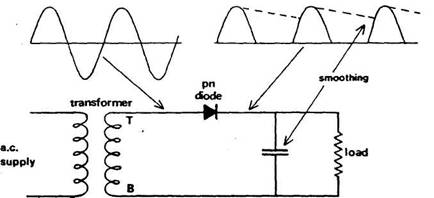
Referring
to the secondary winding of the transformer, when terminal T is positive
relative to terminal B, conventional current flows in a direction that agrees
with that of the arrow symbol representing the rectifying diode. Current
passes through the rectifier to the load and the rectifier is said to be
forward biased. When the situation changes and B is positive relative to T,
then current flow in the circuit would tend to be the other way. This flow is
resisted by the rectifier.
The effect of the single rectifier
is to produce half-wave rectification and, as with alternating current, this can be demonstrated using a
cathode ray oscilloscope. The half sine waves indicate unidirectional although
not continuous flow of current through the load as a result of the pattern of voltage developed. To
obtain a
Full-wave
rectification
Both
half-cycles of the alternating current input can be applied to the load with an
arrangement of two diodes and a
transformer having a centre tap (Figure). Each pn
diode conducts in turn when the end of the secondary winding which supplies it
has full potential relative to the
centre tap.
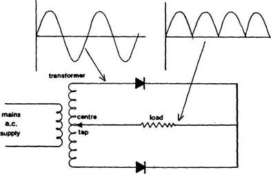
A
high-voltage transformer is needed for this method of full-wave rectification.
The double winding is more expensive than
the cost of extra rectifiers for a bridge rectifier.
Bridge
full-wave rectifier
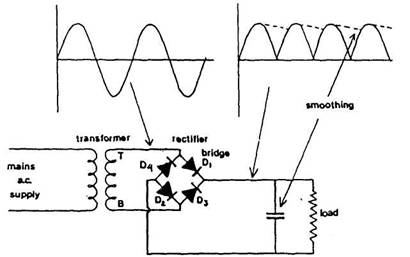
Four
pn diodes in a bridge circuit between the transformer
secondary and the load will give full-wave
rectification without the need for a centre tap (Figure). Transformer voltage and size are smaller for the same output, and the
diodes are exposed to half as much peak reverse
voltage.
The
diodes work in series pairs to complete a circuit carrying current through the
load. When terminal T of the
transformer secondary has higher potential than B, then current follows a path
from T through diode D, to the load and completes its travel through D2 back to terminal B of the secondary. Current flows in the
opposite direction when potential of B is
higher than that of T. The path taken is then from B through D3 to
the load and returning via D4 to
terminal T. A unidirectional current flow is provided for the load and smoothing can be applied to reduce ripple
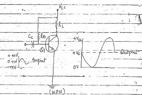
Amplifier
circuit. An amplifier is the device that provides amplification
without appreciably altering the original signal. Amplification
in the process of increasing the strength of a signal. The control by a
small available power over a large usable power is called power gain or
amplification
Transistor can be connected in
different ways and can be used for various purpose
including switching.
Basic transistor amplifier
amplifies by producing a large change in collector current for a small change
in base current. This action result in
voltage amplification because the load resistor placed in series with the
collector reacts to these large changes in collector current which in turn
result in large variation in the input voltage.
8 types of bias used are
Base current bias [fixed bias]
Self bias
Combination
bias. Most widely used because it improves circuit stability and
over comes some of the disadvantages of other 2 type of bias.