Question
Describe with the aid of a simple
sketch the arrangement of the 3 phase winding of an alternator showing the
neutral point.
Explain why for most ship the
neutral is insulated.
Explain why in some installation
the neutral point is earthed.
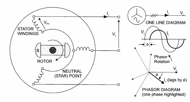
A practical a.c.
alternator [generator] has three sets of coils, called phase windings, located in
slots in the stator surrounding the rotating magnetic poles. The emf induced in each phase is 120" out of phase with the
other two phases. Three phase windings are labelled as U_V_W with colour coding
of red, yellow and blue used on terminals and bus bars. One end of each of the
three-phase winding are joined together to form the neutral point or a star
connection. The other ends of the phase windings are connected to outgoing
conductor is called lines.
Three-phase systems
Outputs from the three sets of
conductors in the alternator are delivered to three separate bus-bars in the
switchboard. This is necessary because of the voltage and current disparity between
them at any instant.
Three-phase, four-wire systems use
a single return wire which is connected to the neutral point of the star
windings. Current in the return wire is the sum of currents in the individual
phases. If loads on each phase are balanced with voltages equal and at 120°
apart, the three currents will sum to zero and the return wire will carry no
current. The fourth (return) wire will carry a small current if there is
imbalance.
Three-phase, three-wire systems
have no return wire. This is acceptable for ships where, direct from the main
switchboard, three-phase motors make up much of the load and unless there is a
fault they take current equally from the phases. Also some imbalance is
acceptable with a three-phase, three-wire system provided load is connected in
delta. Supplies for lighting, heating, single-phase motors and other loads are
taken through delta-star or delta-delta transformers.
The neutral point
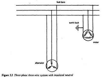
The majority of British ships use
three-phase, three-wire distribution with the neutral points of alternators
insulated (Figure 3.3). Very little current will flow through an earth fault on
one phase, because there is no easy path for it back to the electrical system.
With such a system, an essential electric motor with an earth fault can be kept
running until stoppage for repair is convenient. This would be as soon as
possible to avoid a full-phase fault that would result if an earth occurred on
another phase as well.
Although fault current is
negligible with an insulated/unearthed neutral point, over voltages are high.
The transient likely is 2.5 x line voltage. Such a voltage surge is within the
capability of the main insulation of marine electrical equipment which is
tested to 2 x line voltage-1000 volts.
[If an earth fault occurs on the
insulated pole of an ‘EARTHED DISTRIBUTION SYSTEM’ it would be equivalent to a
‘short circuit’ fault across the load via the ship’s hull.
The resulting large earth fault current
would immediately ‘blow’ the fuse in the line conductor. The faulted electrical
equipment would be immediately isolated from the supply and so rendered SAFE,
but the loss of equipment could create a hazardous situation, especially if the
equipment was classed ESSENTIAL, e.g. loss of steering gear. The large fault
current could also cause arcing damage at the fault location.
An earth fault ‘A’ occurring on one
line of an ‘INSULATED DISTRIBUTOIN SYSTEM’ will not cause any protective gear
to operate and the system would continue to function normally. This is the
important – equipment still operates. The single earth fault does not provide a
complete circuit so no earth fault current will exist.
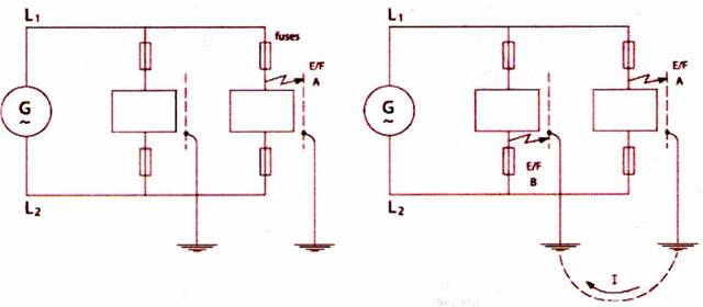
If an earth fault ‘B’ developed on
another line, the two earth faults together would be equivalent to a
short-circuit fault (via the ship’s hull) and the resulting large current would
operate protection devices and cause disconnection of perhaps essential
services creating a risk to the safety of the ship.
An insulated distribution system
requires TWO earth faults on TWO different lines to cause an earth fault
current.
An earthed distribution system requires
only ONE earth fault on the LINE conductor to create an earth fault current.
An insulated system is, therefore, more
effective than an earthed system in maintaining continuity of supply to
equipment.
Hence its adoption
for most marine electrical systems.]
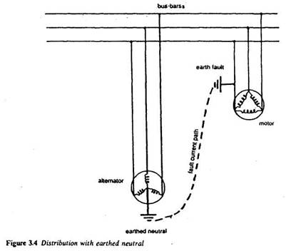
A few British vessels have
electrical distribution systems with an earthed neutral (Figure 3.4). This is a
connection of the system, via the neutral point of the alternator, to the hull steel.
The result of not isolating the electrical system from the hull is that current
flow from an earth fault on any phase has a path through the hull steel and
earthed neutral back to the system. The availability of the path encourages
higher fault current flow than is the case where the neutral is insulated or
connected by resistance.
Equipment with an earth fault,
where the system is earthed, must be disconnected immediately if a fault
develops. This can be effected automatically with an
earthed neutral system because the level of fault current is high enough to
operate a trip.
Earth fault current is high with
earthed neutral systems, but overvoltages due specifically
to earth faults are lower. The earthed system is chosen to limit overvoltages and to give automatic earth fault location and
disconnection.
Overvoltages due to
switching are not affected by choice of earthing or
insulating the neutral. These high surges, and the possibility of others from
failure of the voltage regulator, mean that the same standard of equipment
insulation is required for both arrangements.