Question
What is intrinsic electric safety?
Can live maintenance be done
on intrinsically safe circuit?
Describe intrinsically safe
equipment used on board ship.
Intrinsic safety (IS) is a
protection technique for safe operation of electronic equipment in explosive
atmospheres and under irregular operating conditions. The concept was developed
for safe operation of process control instrumentation in hazardous areas. As a
discipline, it is an application of inherent safety in instrumentation.
The theory behind intrinsic safety
is to ensure that the available electrical and thermal energy in the system is
always low enough that ignition of the hazardous atmosphere cannot occur. This
is achieved by ensuring that only low voltages and currents enter the hazardous
area, and that all electric supply and signal wires are protected by zener safety barriers. Sometimes an alternative type of
barrier known as a galvanic isolation barrier may be used.
In normal uses, electrical
equipment often creates internal tiny sparks in switches, motor brushes,
connectors, and in other places. Such sparks can ignite flammable substances
present in air. A device termed intrinsically safe is designed to not contain
any components that produce sparks or which can hold enough energy to produce a
spark of sufficient energy to cause an ignition. For example, during marine
transfer operations when flammable products are transferred between the marine
terminal and tanker ships or barges, two-way radio communication needs to be
constantly maintained in case the transfer needs to stop for unforeseen reasons
such as a spill. The United States Coast Guard requires that the two way radio
must be certified as intrinsically safe.
Another aspect of intrinsic safety
is controlling abnormal small component temperatures. Under certain fault
conditions (such as an internal short inside a semiconductor device), the
temperature of a component case can rise to a much higher level than in normal
use. Safeguards, such as current limiting by resistors and fuses, must be
employed to ensure that in no circumstance can a component reach a temperature
that could cause autoignition of a combustible
atmosphere.
No single field device or wiring is
intrinsically safe by itself (except for properly designed battery-operated,
self contained devices), but is intrinsically safe only when employed in a
properly designed IS system. Such systems are usually provided with detailed
instructions to ensure safe use.
An intrinsically safe circuit is one that is
designed for a power so low that any spark or thermal effect produced by it,
whether there is a fault or not, is incapable of igniting the surrounding
flammable gas or vapour. It follows that
intrinsically safe equipment is used in such circuits and is designed on the same
basis, i.e. of being unable to produce a spark with enough power to ignite the
specific flammable vapour or gas involved. Intrinsic
safety technique
requires not only that a system is designed for operation with very low power, but also that it is
made invulnerable to high external energies and other effects.
If a fault can adversely affect the
safety of the equipment it is called a ‘countable’ fault. The situation is
further complicated because the apparatus standard permits some specially
designed components to be regarded as infallible and some inadequately designed
features to be failed in normal operation. Consequently there are faults that
are not considered to happen, faults, which are counted, and faults, which are
imposed but not counted.
One of the major advantages of
intrinsic safety is that ‘live maintenance’ on equipment is permitted without
the necessity of obtaining ‘gas clearance’ certificates. A consequence of this
is that during the safety analysis the possibility of open circuiting and
short-circuiting any field wiring is regarded as normal operation. Fortunately
understanding the apparatus standard and faults is only necessary for apparatus
designers and certifying authorities. The apparatus certificates remove the
necessity to consider faults, except for field wiring faults, in system design.
The ability to do live maintenance
on an intrinsically safe system is a major benefit of the technique. It is
difficult to test an instrument system with the power removed, and difficult to
obtain a meaningful ‘gas clearance certificate’ that covers the whole of the
area affected by a system. Consequently live working is very desirable. There
are however factors, other than gas ignition, that have to be considered
whenever an instrument system is taken out of commission and consequently local
safety practices such as ‘permits to work’ have still to be observed.
Permitted practices on the plant
The design of intrinsically safe
apparatus and systems ensures that the short circuit and open circuit of field
wiring cannot cause ignition of a gas atmosphere. The concept of live
maintenance uses this feature but does not extend to carrying out detailed
repairs; for example, repairing printed circuit boards within the hazardous
areas. In practice, the permissible actions are restricted by the available
tools hence deciding what is permissible is not difficult. IEC 60079-17
restricts live ‘working’ to:
i) Disconnection
of, and removal or replacement of electrical apparatus and cabling
ii) Adjustment of any controls
which is necessary for the calibration of the electrical apparatus or system
iii) Removal and replacement of any
plug in components or assemblies
iv) Use of any
test instruments specified in the relevant documentation. Where test
instruments are not specified in the relevant documentation, only those
instruments, which do not affect the intrinsic safety of the circuit, may be
used
v) Any other maintenance activity
specifically permitted by the “relevant documentation”
These requirements are in line with
the normal practice of maintenance on field mounted equipment and hence create
no problem. Work on associated safe area apparatus, such as the intrinsically
safe interface is restricted in the same way, except that there is greater
freedom to operate on the safe area terminals.
Recently developed interfaces tend
to operate from 24V supplies and there is no risk of electrocution. However it
is not unusual for interfaces with relay outputs to be switching higher
voltages, which may create a significant shock risk. Where this risk occurs,
adequate warning labels are required and the relevant precautions should be
taken during the maintenance process. There is no risk of a significant
electric shock being received by a technician working on an intrinsically safe
circuit. There is a hypothetical possibility but in practice this is not a real
problem actions are permitted, they are frequently embodied in the apparatus
certificate and manufacturer’s instruction. This information should be made
available to the relevant technician on the work sheet, as he is not likely to
have ready access to the certificate and/or instructions. The apparatus marking
would carry the ubiquitous ‘X’ marking but this is almost universally applied
and consequently largely ignored.
Permitted practice in the workshop
The repair and testing of
intrinsically safe and associated apparatus should only be carried out in
favourable conditions and by adequately trained technicians. The IEC standard
IEC 60079-19 provides some guidance on the approach to repair of intrinsically
safe equipment. There are always practical and economic limitations on what is
practicable. For example, shunt diode safety barriers are invariably
encapsulated and not repairable. Isolating interfaces are usually in boxes that
are difficult to open, coated in varnish and impossible to test in detail
without specialist test equipment and knowledge of the circuit. In general
replacement by an identical unit is preferred for both economic and safety reasons.
Some repairs can be carried out without affecting the safety of equipment and,
usually, it is obvious what limitations apply. For example, damage to
enclosures does not usually directly affect the intrinsic safety of apparatus
and consequently a repair which restores the enclosure to its original level of
integrity (IP rating) is acceptable. The repair of printed circuit boards is
sometimes considered but is usually impracticable. Removing components without
damaging the board is difficult, repairing the coating on reassembly is messy
and maintaining the original creepage and clearance
distances may not be possible. A recent further complication is that if lead
free solder has been used, the use of solder containing lead usually results in
unsatisfactory joints. A record of any repairs should be maintained. The use of
before and after photographs (stored digitally) frequently simplifies the
process.
Intrinsically safe apparatus is currently made to
two standards of safety. Ex i(a) is the symbol for the higher standard, which requires that
safety is maintained with up to two faults. This type of equipment can be fitted in
any hazardous area. The other standard is given the symbol Ex i(b) and
apparatus made to this specification is safe with up to one fault. The Ex i(b)
products are not used in the most hazardous areas. Manufacturers of
intrinsically safe apparatus state that this method of protection is suitable
for electrical supplies
at less than 30 volts and 50 milliamps. It is used extensively for
instrumentation and
some control functions.
Care is exercised in design that capacitance and
inductance within the electrical installation are kept to a minimum, to prevent storage
of energy which in the event of a fault could generate an incendive
spark. Ex i systems are isolated from other electrical
supplies
even to the extent that the cables are not permitted to be in the same trays as
those of
other cables (to prevent induction effects). Systems are earthed and protection
is provided
by inclusion of shunt diode safety barriers between hazardous and non-hazardous areas
(Figure). The safety barriers have current-limiting resistors and voltage bypassing zener diodes to prevent excessive electrical energies from
reaching the hazardous
areas.
Neither certification nor marking is necessary
if none of the following values are exceeded in a device: 1.2 V,
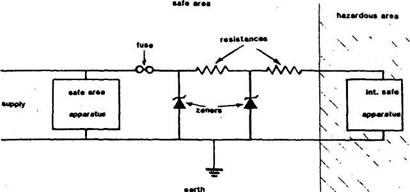
Figure Safety barrier for Ex i equipment