Question
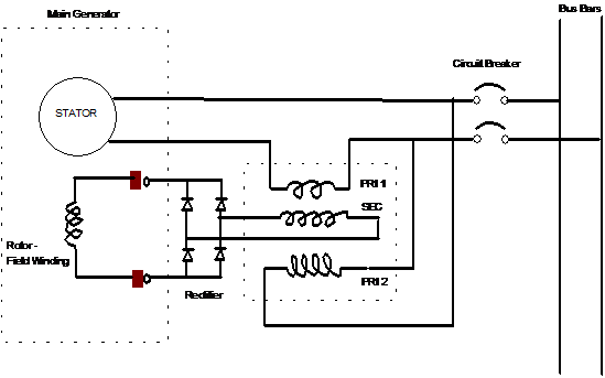
Sketch a diagrammatic arrangement of a static or self excited
alternator.
Static Excitation System (or Functional Type)

The principle of the static or
self-excitation system is that a 3-phase transformer with two primaries, one is
shunt and the other in series with alternator output feeds current from its
secondary windings through a 3-phase rectifier for excitation of the main
alternator rotor.
On no-load, the generator
excitation is provided by shunt connected primary which is designed to give
sufficient main rotor field current for normal alternator voltage at no-load.
Reactor coils give an inductive
effect so that current in the shunt winding lags main output voltage by 90°. Build-up of voltage at starting is assisted
by capacitors which provide a resonance condition with reactors.
On load, the generator current
contributes additional excitation current via the series primary coils. Variation in load current
directly alter excitation and rotor field strength to keep voltage
approximately right.
In this generator, the excitation
system make use of load current from the alternator to supply that component of
excitation current needed to maintain voltage as load increases. This component of excitation is a function of
the load. Field current is thus forced
to adjust rapidly as load changes.
Voltage disturbances accompanying application or removal of load are
greatly reduced. Statically excited alternator have better recovery from voltage disturbance.
State why the voltage dip is less in a self excited
alternator than in brushless or conventional alternator.
Self excited compounded alternator [functional voltage
regulating device] employs control by measuring alternator terminal voltage as
well as by sensing changes in loading conditions by current transformer
A 3 winding 3 phase transformer adds together 2 component of
current
The current obtained from the generator terminals is constant
[for constant voltage] and lags the generated voltage by 90deg because of the
effect of reactor.
The component obtained from the current transformer is
proportional to and in phase with the load current.
The vector addition of these 2 current in the correct
proportion give the correct excitation current under all operating conditions.
The common function is the use of the terminal a.c. voltage for establishing the no load voltage and using
the load current as a means for providing the extra excitation needed to
balance such thing as armature reaction and leakage reactance.
A low voltage dip requires a low sub transient reactance of
the alternator winding but too low a reactance may involve high short circuit
current
The self excited compounded alternator takes care of both and
maintains a low voltage dip as well as keep the short circuit current within
range of available protective gear.
In self excited conventional generator with error operated
voltage control system only terminal voltage is measured and which governs the
excitation control
The absence of load sensing makes it vulnerable to greater
voltage dip and long voltage time.