Question
With reference to hull cathodic protection system of impressed current types
Sketch and describe such a system.
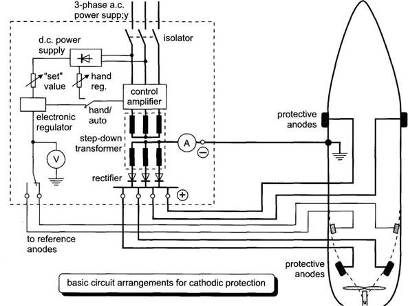
Cathodic protection
systems fitted in ships consist of a number of anodes (lead or platinised
titanium) fitted to the hull at selected places below the waterline, and control
equipment which automatically regulates the anode current to the required
value. Direct current is supplied to the anodes, after transformation and rectification,
from the ship's 440 V 60 Hz 3-phase a.c.
distribution system. The control equipment comprises reference electrodes,
an amplifier assembly and one or more transformer rectifier units.
The anode current control is
usually regulated by electronic thyristor controllers
and the diagram in Fig. outlines a typical scheme.
The control equipment automatically
monitors the size of anode current required which will vary with the ship's speed,
water temperature and salinity, condition of paint work etc. Typical anode current
densities range from 10 mA/m2 to 40 mA/m2 for the
protection of painted surfaces and 100 to 150 mA/m2 for bare steel surfaces.
The total impressed current for a
hull in good condition may be as low as 20 A. Maximum controller outputs may be
up to about 600 A at 8 V.
Explain how protection may be
ensured for the rudder and propeller.
To ensure that the rudder,
propeller screw and stabiliser fins receive the same degree of cathodic protection as the hull it is necessary to
electrically earth-bond these items to the hull. The rudder stock may be bonded
by a wire braid linking the top of the stock to the deck head directly above
it. Carbon brushes rubbing on the rotating main propulsion shaft effectively
bond the shaft to the hull. A periodic inspection of such earthing
is worthwhile as the brushes wear away and may occasionally stick in their
brush holders.
State any precaution that should be
taken when this type of system is installed.
Measurements should be regularly
logged together with the ship operating conditions, e.g.
location,
draught, water temperature, etc.
Changes in underwater hull area, speed, water temperature/ salinity and paint
condition will all cause the anode currents to vary. The hull potential should,
however, remain constant in a properly regulated system. Although the reference
electrodes and the monitoring facilities give a reasonable day to day check
they are only measuring in the vicinity of the fitted electrodes.
When the ship is moored singly or stopped
at sea, voltage readings can be taken between a portable
silver or zinc test electrode and the ship's hull. This portable electrode is
lowered 2-3 metres below the water surface and as close as possible to the hull
at specified positions around the ship.
Check the manufacturer's
instructions regarding the storage and setting up of the portable electrode.
Some have to be immersed in a plastic bucket of sea water for about 4 hours
before the hull test. With the cathodic protection switched
on and working normally, the voltage measured between hull and a silver/silver
chloride portable electrode should be 750-850 mV using a high resistance multimeter (e.g. analogue or digital type); the electrode
being positive with respect to hull.
When dry docked, ensure that the main
anodes and reference electrodes are covered with paper tape to prevent paint
contamination.