Question
With
reference to fluorescent lamps.
Describe a switch type starter.
Describe a transformer quick start.
List two reasons for inclusion of
capacitor to fluorescent light circuit.
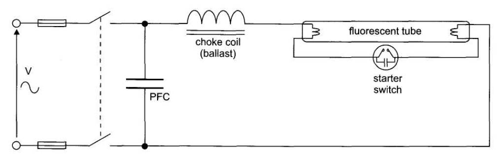
The circuit in Fig. shows a typical
switch-start circuit.
The starting action is initiated by
a glow type starter switch which is connected between opposite ends of the
tube.
When the supply voltage is applied
to the circuit, the full mains voltage appears across the
starter switch. A glow
discharge occurs between the starter contacts which
quickly heat up, bend and touch each other. This allows current to flow through
the lamp cathodes which will cause the tube ends to heat up and glow before the
tube actually strikes. The tube strikes when the starter switch re-opens as it
cools down during its closed (non-glow) period. When the starter switch opens
it interrupts an inductive coil (choke) circuit which produces a surge voltage
across the tube which then strikes.
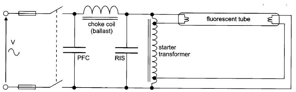
Fig. Transformer-start
fluorescent lamp circuit
The lamp discharge begins as soon
as the cathodes reach their operating temperature. A capacitive effect between the
cathodes and the earthed metalwork of the fitting ionises the gas and the tube strikes
very quickly
Capacitors are used with discharge
tubes for:
Power factor correction (PFC)
Radio
interference suppression (RIS).
The PFC capacitor is used to raise
the supply power factor to around 0.9 lagging. Without this capacitor the power
factor may be as low as 0.2 lagging due to the high choke-coil inductance to cause
the supply current to be 4 to 5 times larger than normal.
Radio interference from discharge tubes is
caused by the ionisation process of the discharge through the tube. This is suppressed
by a capacitor fitted across the tube ends. In glow-switch circuits, the RIS
capacitor is actually fitted within the starter. Typical RIS capacitor values are
around 0.0005 µF.