Question
Sketch a diesel electric propulsion
arrangement for a ship
Describe the operation
Outlining how reversal of the
propulsion motor is achieved.
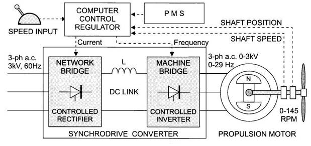
In a synchrodrive
system as shown in Fig., the computer receives a command (set speed) input and
many feedback signals (voltage, current, power, frequency etc.) but the obvious
regulating item is the actual shaft speed feedback forming a closed control
loop.
The principal parameters to be
controlled are the size of motor stator current (to set motor torque) and the
motor frequency to set the shaft speed.
In addition, the
In normal running and full-away
with both propulsion motor speeds within 5% of each other, the bridge can
select a shaft synchro-phasing mode which applies momentary
acceleration/deceleration to bring the propeller blades into an alignment
which minimises shaft vibration into the hull.
Speed and position are derived from
detectors on the non-drive end of the motor shaft.
At speeds of less than 10%, the
motor does not generate sufficient back e.m.f. to
cause automatic thyristor switch-off (line
commutation)
A thyristor
can only switch off when its current becomes zero.
This problem is overcome by pulse-mode
operation where the current is momentarily forced to zero by the thyristors in the controlled rectifier stage.
This allows the inverter thyristors
to turn-off so that the controller can regain control.
The decision is now which thyristor and which sequence of switching is required to
maintain the required shaft direction of rotation.
It is necessary to know exactly the
position of the rotor poles and this is provided by the shaft position encoder
for low-speed, pulse-mode operation.
When kicked above 10% speed, the
motor e.m.f. will be large enough to allow the
converter to revert to its normal line-commutation mode for synchronous operation
For normal running, above about 10%
speed, the operation is switched to synchronous mode where the thyristors in both bridges are switched off naturally (line
commutated) by their live a.c. voltages from supply
and motor
To reverse the shaft rotation the
forward/ ahead phase sequence of motor supply currents is reversed by the
inverter thyristors.
This reverses the direction of stator
flux rotation and hence shaft direction to astern.
The rate of deceleration to zero
speed must be carefully controlled before a shaft reversal to avoid large power
surges in the system.
For a motor braking operation, the inverter
bridge can be considered as a rectifier bridge when viewed from the live a.c. supply produced by the motor emf.
If the network (rectifier) bridge thyristors are switched with a delay angle greater than 90°
the d.c. link voltage reverses causing power flow
from the motor back to the supply (motor braking).
In this mode the roles of the
network and machine bridges are swapped over.