Question
With reference to time lag in the
operation of over current protection devices
Describe 2 methods of obtaining time
lag
Explain the purpose of time lag.
Explain discrimination with respect
to electrical distribution system.
Explain inverse current time
characteristic
Methods of obtaining time lag
Thermal
Electronic
All methods have an inverse
current-time characteristic, i.e. the bigger the current the faster it will
operate.
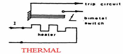
A thermal relay utilised the
bending action of a bimetallic bar to trip the circuit-breaker. The time taken
to heat the bimetal gives the necessary time lag.
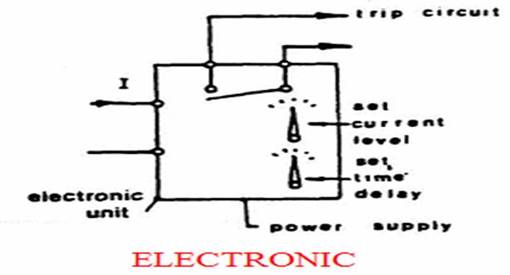
An electronic over current relay
usually converts the current into a proportional voltage. This is then compared
with a set voltage level within the transistorised monitoring unit. The time
delay is obtained by the time taken to charge up a capacitor. This type of
relay usually has separate adjustments for current trip level and for trip
time. The amplifiers within the electronic relay can be set to give an almost
instantaneous trip (typically 0l05 sec) to clear a short-circuit fault.
Purpose of time delay
To delay tripping
To allow current surges for motor
starting and generator synchronizing
Also time delay
are required with short circuit devices to give discrimination.
The over current relay must be
provided with a short time delay even when responding to a short-circuit
condition, to maintain discrimination with the feeder circuits. Because of this
delay the relay will usually respond only to the steady-state short-circuit
current. If the relay operating current is too high, or if the fault current if
too low, the circuit breaker may be tripped only after an excessively long
time. Therefore, to ensure satisfactory operation of the protective equipment,
the generator specification often calls for a minimum steady-state fault
current capability of three or four times the full-load current when the
machine is warm.
The time delay under short-circuit
conditions is usually between 0.1 and 3.0 seconds, the actual setting depending
on discrimination requirements.
Discrimination.
The ability of a protection system
to disconnect only the faulted circuits and to maintain the electrical supplies
to healthy circuits is called protective discrimination.
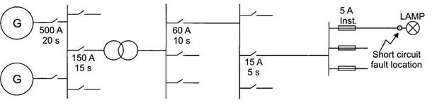
Discrimination is achieved by coordinating
the current ratings and time settings of the fuses and overcurrent
relays used between the generator and the load as shown in Fig. The protective devices nearest the load having the lowest current
rating and shortest operating time. Those nearest the
generator having the highest current rating and longest operating time.
If a short-circuit fault occurs in
the lampholder in Fig. the fault current will be
large enough to operate all protection devices from the generators to the
fault. However, the 5 A fuse protecting the lamp
circuit has the lowest current rating and shortest operating time in the system
so will be the quickest to operate. This action will clear the fault and leave
all other healthy circuits still connected.
Inverse
current time characteristic.
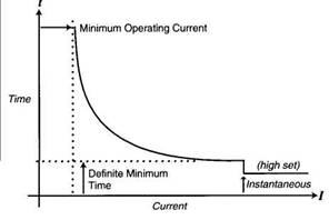
All relay types have an
inverse current-time
characteristic called OCIT (over-current
inverse time), i.e. the bigger the current
the faster it will operate. See Fig.
The basic inverse I/t curve would
tend towards zero time for the highest
currents. To make the relay action
more precise at very high fault currents the action is arranged to operate at a definite minimum time which is fixed by the design. This type is called an OCIDMT (over current inverse and definite minimum
time) relay action.