Question
Describe the characteristics of a DC motor
Explain the advantages of such a DC motor for deck
machinery
Describe with the aid of a sketch a control system for
the motor in a
The characteristics of
Shunt or lightly compounded motors are suitable for
fans, pumps, etc., and variable speed is obtained economically, i.e. without
loss of overall efficiency, by shunt regulation.
Up to four-to-one speed variation is obtainable but
three-to-one is the more usual limit.
Where a wider range is essential it can be obtained by
a series resistance in the armature circuit.
For very low creeping speeds a series resistance and a
diverter resistance across the armature may be used.
When a wide range of speed is obtained by shunt
regulation it is necessary to ensure that the motor is not started with a
weakened field.
This would reduce the starting torque and cause
sparking at the commutator.
The regulator must be interlocked with the starter so
that it must be returned to the full field position before starting.
Series wound motors are used where a high starting
torque is required, such as for engine-turning gear, winches, windlasses and
capstans, boat winches, etc. The speed varies with the load and such motors
should never be run without load as the speed becomes excessive.
Sometimes a light shunt field is incorporated in order
to limit the light running speed.
Winches and capstans incorporate special control
equipment for dealing with the wide range of load and speed which-is necessary
for successful operation.
Ward Leonard systems are sometimes employed when a
wide speed range is required such as for winches.
In this system the motor is separately excited and the
armature is connected to a generator, the voltage of which can be varied.
The control is therefore on the shunt winding of the
generator and as the field currents are comparatively small the control gear is
correspondingly small. This system also has the advantage that very fine speed
control is obtainable from zero to full speed.
Motor Characteristics
The characteristic curves of a motor are those curves which show relation between the
following quantities :
(1) Torque and
armature current i.e. Ta/Ia characteristic. It is also known as electrical
characteristic.
(2) Speed and
armature current i.e. N/Ia characteristic.
(3) Speed and
torque i.e. N/Ta characteristic. It is also known
as mechanical characteristic.
This can be found from (1) and (2) above.
COMPARISON OF DC MOTOR CHARACTERISTICS
The characteristics of dc motors should be considered
when selecting motors for particular applications. Figures 8-11 and 8-12 show
comparative graphs that illustrate the relative torque and speed characteristics
of dc motors,
Torque relationships. A comparative set of
torque versus armature current curves for dc motors is shown in Figure 8-11, The effect of increased mechanical load on the shaft of
each type of motor can be predicted.
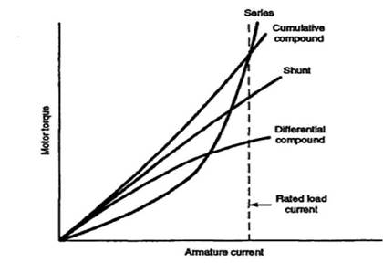
Figure 8-11 Torque versus armature current curves of
dc motors.
Series-wound dc motors have equal armature current,
field current, and load current (IA = lFI = II). The
magnetic flux (Φ) produced by the field windings is proportional to the
armature current (IA). The torque produced by a series-wound motor with low
values of IA is less than other motors due to lack of field flux development.
However, at rated full-load armature current the torque is greater than other
types of etc motors.
Shunt-wound dc motors have a fairly constant magnetic
field flux due to the high-resistant field circuit, an
almost linear torque versus armature current curve is a characteristic of
shunt-wound dc motors. Since torque is directly dependent on armature current,
as 1A increases, torque increases in direct proportion.
Compound-wound dc motors are of two general types:
cumulative and differential. Cumulative compound dc motors have series and
shunt field windings which aid each other in the production of an overall
magnetic field. In this type of motor circuit the general torque equation is: T
= K (Φs + Φp) IA,
where Φs is the series
field flux and ΦP is the parallel (shunt) field flux. The series field
flux increases as IA increases and the shunt field flux remains fairly constant
There fore, the torque curve (see Figure 8-1 1) for a cumulative compound dc
motor is always higher than that of a similar shunt-wound dc motor.
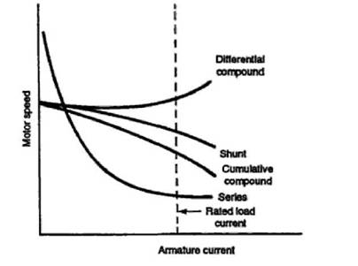
Figure 8-12 Speed versus armature current curves
of dcmotor
Advantages
Series motors are variable speed machine giving a low
speed on heavy loads.
They are ideal for traction, winch, hoist, and fan
Their excellent starting torque characteristic can be
used advantagesously where masses have to be accelertated quickly as for lifting or traction
Control system for D.C. motor.
Ward-Leonard system.
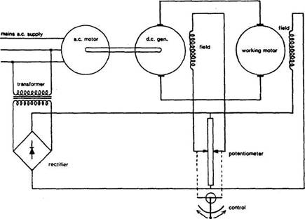
This system, used for fine control of
The system was used for the motors of electric (as
opposed to hydraulic) steering gears of ships with
The working motor (Figure) which powers the steering
gear, windlass or other equipment is a d.c. machine,
because speed control of these is easy.
The method is to alter the voltage applied through the
brushes to the armature windings of the
The voltage is increased or decreased, not with the
use of resistances but by arranging an individual
Speed and
direction of the working motor vary with the magnitude and direction of applied
voltage.
Current for the windings of the field poles is derived
from the source of main power.
Where there is a.c. main power, current for the windings is transformed to lower
voltage and rectified.
The
Output of the generator is varied by changing the
current to its field windings through a variable control resistor
(potentiometer).
As magnetic field strength is altered by the change of
field current, so too is the generated voltage. Switch of direction of current
flow through the field poles, also with the potentiometer, will cause the
direction of the pole magnetic fields to change. This changes
the direction of generated current supplied to the motor and thereby also the
running direction of the motor.
The control lever can, by moving the potentiometer
contacts in opposite directions away from the mid-position shown in the sketch,
set the polarity and strength of the generator field poles.
By governing generator output to the armature of the
working motor, this in turn gives stepless speed
control of the working motor, in either direction.
The system as used for steering gear operation on