Question
Describe how the AVR monitors out put and controls the
excitation system
Sketch a circuit diagram for AVR and how AVR utilize a silicon controlled rectifier to control the excitation
system for an alternator.
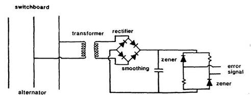
Figure a Static automatic voltage regulator {SA VR
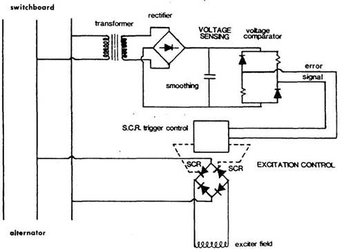
Figure b. Error signal used to control thyristors
in the excitation system
The direct current derived from the alternator output is
applied to a bridge (Figure a) which has fixed resistances on two arms and
variable resistances (zener diode voltage references)
on the other two.
The zeners operate in the reverse
breakdown mode, voltage of very low value.
As can be seen from the earlier description of zener diodes, voltage remains constant once breakdown has
occurred despite change in current.
This implies, however, that changes in applied voltage, while
not affecting voltage across the diode, will cause a change in resistance which
permits change in current. As with a Wheatstone bridge, imbalance of the
resistances changes the flow pattern and produces in the voltage measuring
bridge an error signal.
The error signal can be amplified and used to control
alternator excitation in a number of different ways. Thus it can control the
firing angle of thyristors (Figure b) through a
triggering circuit to give the desired voltage in the brushless alternator
described. It can be used in the statically excited alternator to correct small
errors through a magnetic amplifier arrangement. The error signal has also been
amplified through transistors in series, for excitation control.
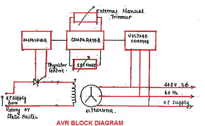
Sudden load current surges in a
generator causes
a voltage dip. Load shedding produces an overvoltage at bus bar. Such
fluctuation is undesirable and AVR is required to rapidly correct such voltage
changes. The AVR senses the generator out put voltage and acts to alter the
field current to maintain voltage at the set value. Manual trimmer regulator
may be fitted on the generator control panel to set voltage level.
The voltage sensing unit transforms down, rectifies, and
smooth the generator output voltage
This produces a low voltage DC signal proportionate to AC
generator voltage. In comparator unit it is compared with the set value [dc
value produced by reference unit of zener diodes and
reactance]
The correction is then amplified and through thyristor control is used to alter the alternator field
current in order to reach the set voltage value.
Additional component and sub circuit are included in the AVR
to ensure.
Rapid response time with voltage stability
Fair current sharing, when generator are running in parallel
Quick voltage build up during generator run up
Over under voltage alarm trip
protection.