
Oil contamination in marine boilers
Inadvertently mixing oil and water may lead to burnt down boilers
General
An oil-fired steam boiler onboard a ship is fed by returned, condensed steam to replace the boiled off water as well as with stored make-up water to replace steam lost by consumption, leakage or blow-down.
The feed water is normally treated mechanically and chemically in order to suit the steaming process in the boiler and to ensure good transfer of the heat input from the combustion process to the water.
A closed cycle process would be preferable in order to ensure a heat transfer of high efficiency, but for investment reasons such systems are practically non-existent in today’s auxiliary boiler installations.
Types of contamination
A ship contains heat exchangers for bunker fuel and cargo liquids, heating coils and seawater coolers. So when steam from the boiler and condensed steam circulate through the ship’s system, it is almost inevitable that foreign substances like heavy fuel oil, lubricating oil and seawater will influence the boiler water quality due to leakage.
A contamination could form deposits on the boiler tubes or furnace walls that are swept by the flames on the opposite side.
With seawater it is well known that chlorides will form a very hard layer of lime deposits if the contaminated feed water is not treated sufficiently.
Also, make-up water bunkered ashore might contain humus particles and silica, forming heating surface deposits when heated.
Oil as a contaminator
The most dangerous water contamination, however, is heavy fuel oil entering the steam or condensate from leaking tank coils or heat exchangers.
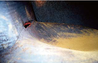
This kind of leakage in coil flanges or broken gaskets in plate heat exchangers frequently occurs. If the problem is not observed in time, the boiler could be completely destroyed due to overheating of the furnace because of reduced water flow and minimised heat transfer/cooling of the boiler tubes.
The isolating effect of oil deposits reduces heat transfer much more than e.g. a limestone scale layer of equal thickness. To understand the mechanism, we have to focus on the metal temperature as well as the conductivity of the metal and the different types of deposits.
The conductivity of steel can be set to 50 W/m2 °C, scale having 2 W/m2 °C and oil 0.1 W/m2 °C. It follows that oil isolates 20 times as much as scale, with the same thickness of deposit.
The strength of the steel material will be reduced with increased temperature. An example shows that the material strength in an auxiliary boiler will be reduced to 1/3 of its original design value by an oil deposit of only 0.5 mm thickness. The steel material starts scaling at the fireside, when it is not cooled sufficiently and will soon rupture with great damage as the consequence.
First damage control action (boiler)
The first preventive action to be taken when oil leakage into the feed water system is suspected is to take a look in the cascade or hot well tanks. If oil is found in the last compartment just before the water enters the feed water piping, it is recommended to check whether a dark oily film contaminates the boiler water level glasses inside.
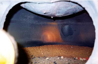
If so, do not blow down the boiler from the bottom; just surface blow several times. If you bottom blow the boiler, it will become totally covered in oil. The boiler should be shut down and released from pressure and the venting valve opened.
Afterwards, the boiler can be drained slowly until water stops flowing from the loosened, upper manhole door before opening up the manhole for inspection. The oil will now only cover the boiler in the normal water level range and can be manually removed.
Hot or cold water high-pressure jet equipment together with oil dispersive additives would be efficient for removal of the oil.
In case the boiler is completely oily inside, the cleaning work could be turned over to a cleaning company specialised in such work.
First damage control action (ship)
A careful examination and hydro test of all suspected heating coils, heaters or whatever is leaking in the steam/condensate system. Be aware that even when one leakage is found, there could be several more remaining. When it is assured that no more leakage can be found, the piping system, coils and heaters have to be cleaned of all remaining oil. The oil-fired boiler must not be started up again until an oil-free feed water supply is guaranteed.
Preventive action
The feed water/hot well/cascade tanks have to have filters installed, filled with lofa sponges, coconut fibres or similar, which effectively take up small amounts of oil. The filter inserts have to be exchanged regularly according to demand. The cascade tank can easily be equipped with a continually measuring oil detecting device which monitors if oil is present in the condensate. By locating the sensor in the cascade tank, it can be assured that oil is detected before it enters the feed water section, which means that no part of the feed water is being contaminated.
A more comprehensive system for preventing oil from entering the boiler would be to transmit a signal to an air- or electrically operated three-way valve switching over the condensate flow to the bilge until the oil source is pinpointed and eliminated. An investment in such equipment pays off quickly because it prevents the boiler from serious damage by burnt down tubes and furnace room plates.
Three examples are made to illustrate the increase in temperature of the furnace wall when the waterside of the furnace is fouled with sediments of 2 mm carbonate, 0.5 mm silica, or 0.5 mm oil film:
In conclusion, the maximum temperature of the furnace wall is increased from 256°C to 633°C with an oil film of just 0.5 mm. Furthermore, the transferred heat is reduced from 137 kW/m2 to just 82.3 kW/m2, a reduction of 40%.
No sediment 2 mm carbonate 0.5 mm silica 0.5 mm oil film
a0 [W/(m2 x K)] 10,000 10,000 10,000 10,000
l1 [W/(m x K)] - 1.72 0.172 0.10
l2 [W/(m x K)] 38 38 38 38
a3 [W/(m2 x K)] 145 145 145 145
S1 [mm] - 2 0.5 0.5
S2 [mm] 20 20 20 20
atotal[W/(m2 x K)] 133 115 95.8 79.9
Q [kW/m2] 137 119 98.7 82.3
T0 [°C] - 181.9 179.9 178.2
T1 [°C] 184 320 467 590
T2 [°C] 256 382 519 633
Water
170°C
7 bar(g)
Furnace
1200°C
Temperature of furnace wall with sediments on water side If the waterside of a furnace wall is fouled with e.g. carbonate, silica, or oil film, the temperature of the furnace wall increases due to added thermal resistance.

