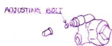
Pressure Jet Straight Type Atomizer
General
(1) This burner is designed to perform automatic iqnition/ extinguishment and HI/LOW combustion in accordance with the boiler pressure to maintain constant boiler pressure,
Type of the atomizer is pressurejet straight type. Variable burner combustion rate is available by varyinq the fuel injection pressure and by changing the atomizer, as necessary .
(2) This burner comprises the F D. fan , F.O. pumg F.Oheater, pressure switvhes and the control panel.
(3) The burner control panel is provided with the control circuit to facilitate automatic operation of the burner and also the manual operation switch.
2 . Burner Operating Sequence.(Automatic 0peration)
(1) Upon receipt of the start signal by the burner, the F.O. pump and the F.D. fan start operatinq simultaneously with start of the cam timer, and oil which enters the burner unit circulates in the route of the strainer + F.O. pump+F.O. heater + sprayer body outer tube + return pipe and simultaneously commences furnace pre-purging.
(2) The pilot burner unit is actuated for 49 - 59 sec. in 49 sec. after pre-purging to thereby perform ignition to the pilot burner. Ignition of the pilot burner allows working of the flame eye to illuminate the combustion indicating lamp.
(3) Ignition of the main burner is available by actuation of the ON/OFF solenoid valve in 50 sec.
(4) After the main burner comes into combustion, the cam timer stops at the position of 71 sec. to allow continuous combustion of the main burner. The HI/LOW pressure switch set at the ill setting value during continuous combustion opens the HI solenoid valve to perform combustion by two atomizers No. 1 and No. 2.
(5) When the boiler pressure reaches the LOW settinq pressure
of the HI/LOW pressure switch, the HI solenoid vale is closed for changeover to low combustion by No. 1 stomizer only. When the boiler pressure furher rises to reach the OFF setting pressure of the ON/OFF pressure switch, the ON/OFF solenoid valve becomes OFF for automatic extinquishment. The burner stops after conducting post-purge (49 sec.) and
the burner is put in the stand-by state. Then, reduction of the boiler pressure to the ON (start) setting pressure allows automatic combustion of the boiler in the sequence as described below.
In the event that the heater becomes ON while the burner is in stand-by position, automatic run of the motor is available to thereby circulate oil for heating of the oil pipe, and the motor is kept running during the time set by the timer
after the heater becomes OFF.
(6) In case of ignition failure of the main burner in 10 sec. and detection failure of combustion by the flame eye, the burner is immediately locked out to illuminate the non-ignition indicating lamp and sound the alarm. The F.D. fan is stopped after post-purge of furnace (60 sec.). Re-start is unavailable so far as the non-ignition indicating lamp is illuminating. Therefore, find the cause for non-ignition and conduct resetting before re-starting.
(7) The F.O. heater is provided with thermostats for low oil temp., temp, control and safety whereby the oil temp, is controlled by the temp, adjusting thermostat so that combustion of proper-temp, oil is achieved.
3. Igniting Operation
In the event that ignition is trie3 for the first time or when the oil pipe line becomes empty, verify the following points before conducting ignition.
(1) Check if the atomizer is duly fitted to the sprayer body and if the dimensional relation between the swirler and the throat ring is correct.
(2) Check if the ignition electrode and the pilot burner are correctly mounted.
(3) Check if fuses for all circuits, magnetic switcehs and the thermal relay on the control panel are normal.
(4) Check if the boiler pressure switch is set at specified pressure.
(5) Open the air vent valve provided on the heater top to check if the heater is filled with oil.
The burner operation is available by pressing the start switch after completion of the above verification and equipment adjustment as described in Section 5.
4. Operating Method of Manual Operation Switch
The manual operation switch is intended for use for verification of start of ignition and troubles. (Normal use is prohibited.) Don't fail to observe visual watching in front of the boiler, as the interlock does not work.
(1) Operating sequence
(a) Turning of the F.D. fan operating switch in "MANU.ON" mode allows the fan and the motor to start running. At this time, verify oil pressure and oil temperature and conduct pre-purge more than 30 sec.
(b) Turning of the ignition operating switch on "MANU.ON" mode allows start of ignition and running of the pilot burner to illuminate the combustion indicating lamp.
(c) Turning of the heavy oil solenoid valve operating switch in "MANU.ON" mode allows opening of the ON/OFF solenoid valve so that oil is injected into the furnace to achieve combustion of the main burner.
After 5 sec., turn the ignition operating switch in "AUTO." mode to stop the pilot burner, and verify continuous combustion of the main burner only. (In the event of ignition failure of the main burner, conduct purging of the furnace and then find out the cause for the ignition failure.)
(d) Turning of the HI/LOW control operating switch in the "MANU.ON" mode allov* changeover to the HI combustion position to thereby see combustion by No. 1 and No. 2 atomizers.
Completion of the above operations facilitates manual operation. For extinguishment, turn the switches in "AUTO." mode in order of (d), (c) and (a).
(2) Other manual operation switch and terminal
(a) Heater ON/OFF switch
Turning "ON" of this switch facilitates adjustment of oil temperature by means of the temp, adjusting thermo-stant housed in the heater.
(b) Flame eye by-pass terminal (Rl) (40)
This terminal is intended for use when the flame eye is out of order to show abnormality of the flame detecting circuit such as illuminatinq failure of the combustion indicating lamp in spite of ignition of the burner.
Short-circuiting of the terminal (Rl) (40) shows combustion state. Therefore, running of the burner is available by means of this short-circuiting, even if the flame detecting circuit is out of order. However, no protection is provided against flame-out and therefore, don't fail to conduct visual watching when the burner is thus operated.
5. Adjustment of Burner Equipment U) F.O. pump pressure
(1)Keep the burner in combustion and adjust the F.O. pump pressure to 20 kg/cm by turning the bolt of the relief valve provided in the pump.

(2) F.O. pump suction pressure
In the event that a booster pump is installed, adjust the pressure to 1 - 2.0 kg/cm2 by means of the safety valve and the relief valve.
In case of absence of the booster pump, maintain the pressure above 0.2 kg/cm2 , as reduction to below 0.2 kg/cm2 causes vacuum condition.
(3) Pump pressure for pilot burner
(a) Turn the F.D. fan operating switch in "MANU.ON" to run the fan.
(b) Turning of the ignition operating switch in "MANU.ON" allows start of rotation of the pilot pump with simultaneous spark production at the electrode tip to ignite the pilot burner.
Adjust the pressure to 15 - 20 kg/cm2 by means of the relief valve houses in the pilot pump.
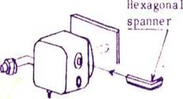
Variation of pressure is available by turning of the adjust screw on the relief valve with a hexagonal spanner.
(4) Damper
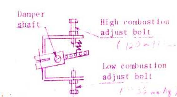
The damper is kept opened at predetermined opening dearee for low combustion and ignition. For high combustion, the damper is further opened by solenoid to increase the air quantity. For adjustment, mount a U-tube manometer and adjust the wind pressure by means of the adjust bolt so as to achieve the wind pressure corresponding to the combustion rate. In the event that adjustment is unavailable by means of the bolt, vary the damper shaft angle and try adjustment again by means of the adjust bolt.
(5) Thermostat temperature
Refer to the heavy-oil viscosity-temperature reflation chart appended hereto and set the thermostat to the temperature whereby the oil viscosity becomes R.W.No.l, 80 sec.
(Example) In case of use of oil of 1500 sec. & (3500 sec.) on R.W. Ho. 1 at 38°C
Temp, adjusting thermostat 1000°C (115°C)
Low oil temp, thermostat 80°C ( 90°C)
Safety thermostat 140°C (150°C)
6 . Troubleshooting
(1) Burner ignition failure
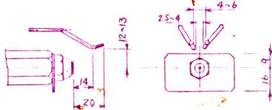
[a) In the event that ignition of the pilot burner is unavailable, remove contamination from the electrode and the porcelain insulator and check if dimensional relation of the electrodes is as given below and adjust if necessaray
(b) In case of spark production failure at the electrode tip due to flawed electrodes for high-voltage current transmission for ignition purpose or due to flawed plug insulators, allow them to be cleaned of contamination
or replace with spares.
(c) In case of atomizing failure or abnormal atomizing of fuel from the atomizer, even though the pilot burner oil pressure remains as adjusted, remove the pressure valve housed in the burner body. In the event of good ignition, such abnormality is due to flaw on the pressure valve. Check the valve seat for flaw for corrective action, if necessary. In the event that proper atomiza-tion is still unavailable, get rid of the pressure valve, as this pilot pipe line is provided with a pressure valve housed in the pilot pump as well, ensuring no oil leakage.
(d) Inclusion of heavy substance or water in pilot fuel causes difficulty in ignition of the pilot burner. Therefore, take care for property of pilot oil.
(e) Too low temperature of ful oil to be burnt in the main burner causes difficulty in ignition. In such a case, therefore, raise the oil temperature.
(f) Coming-out failure of oil from the solenoid valve is due to insufficient power voltage or clogging of the solenoid valve with dust. Check and take corrective actions .
(g) In case of excessive wind pressure during ignition, reduce the wind pressure.
(h) Flame detection failure by flame eye
-1. Wipe out contamination the flame eye lens with cloth
-2. Check if the lead wire is not disconnected and if the pin inserted into the socket is in perfect contact status. Take corrective actions, if improper,
-3. Performance failure of the relay even by linking of the terminal (F&D) is due to the faulty flame detector relay. Replace with a spare.
-4. Connect a tester ohm meter to the terminal (F&D). Indication of 5 - 4OKohm on the meter when light is applied on the flame eye and above 500 Kohm in case of absence of light means that the cds is good for performance. Indication of other values than stipulated above tells that the cds is faulty. Replace with a spare.
(i) Actuation of sprayer cut-off valve
Overhaul the sprayer for cleaning. Replace with a spare, if the valve seat is found improper.
(2) Extinguishing failure of burner
(a) Check the solenoid valve for flaw on the valve seat or clogging with dust for overhaul cleaning, as necessary.
(b) In the event that operation of the flame eye does not become OFF, check the circuit.
(c) In case of large flaw on the sprayer cut-off valve seat causing continuous oil leakage irrespective of reduced oil pressure to thereby result in extinguishing failure, replace the valve with a spare or repair the packing seat surface to be flat.
(3) Flame failure of burner
(a) In case of improper oil temperature, vary setting of the relevant thermostat for correction.
(b) In case of flame blow-out due to excessive wind pressure, reduce the wind pressure.
(c) In the event that the swirler and the throat ring are contaminated with carbon, conduct overhaul cleaning.
(4) F.O. pressure rising failure
(a) Check if oil is fed into the burner.
(b) Check for normal operatior of the relief valve.
(c) In case of reduction in the pump discharge rate, conduct replacement of the relevant parts with spares.
(5) Smoke production
(a) Raise the wind pressure, if smoke production is due to insufficient air quantity.
(b) Low oil temperature causes improper combustion. In this case, therefore, raise the oil temperature.
(c) See the atomizer number to check if it is normal products. Furthermore, reduce the oil pressure to see if smoke is produced. Also, check if smoke is produced, using another type atomizer.
(6) Improper heater control
(a) Heating failure in spite of continuous power supply to the heater element is considered due to the faulty element. Replace with new one.
(b) Fully closed needle valve provided on the heater by-pass valve retards the oil temperature rise. Therefore, keep the needle valve opened during operation.
(c) In the event that large oil temperature difference is seen during combustion after setting of the thermostat, removal of the heater power source terminal (Wl) only from the control panel may facilitate lessening of the temperature difference. In this case, take care so that the removed wire does not get in contact with other parts. But, in the event that the above method causes insufficient heating capacity, return the wire to the original state.
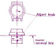
(d) In the event that the thermostat dial indicates different temperature from the thermometer indication, setting shall be conducted with the thermometer indication as correct. But, in case of excessively wide difference, correction is available by the following procedure.
Set the thermostat dial to 110°C. And, if the thermostat sends START or STOP signal at the position of the temperature indicationy of 80°C the discrepancy is due to the setting error of the dial switch and the sensor proper. In this case, correction
is available by turning the knob provided on the heater body clockwise so that the switch becomes ON at 110°C at which the thermostat is set to work.
7. Maintenance and Inspection
(1) Allow periodic check of the swirler, ignition electrodes and burner tile for deposition of oil scale, carbon, etc, for cleaning and dimensional check, as necessary.
(2) Maintenance of atomizer
An atomizer, flawed or after long period use, causes uneven atomization and large atomized particle size to result in poor combustion. Take care for the shape of the atomizer and flaw, and replace with a spare when abnormality is found. Flawed contact face of the atomizer at the flat contact part of the sprayer body tip metal may cause oil leakage. Therefore, take strict care not to allow a flaw thereon. In cleaning the atomizer, use copper cire or wood.
(3) Solenoid valve
Run the pump manually and loosen the solenoid valve secondary side joint to check the solenoid valve is in securely closed position to permit no leakage of oil.
(4) Open the peep window cover for the burner side coupling to check the coupling for existence of abnormality and inclusion and deposition of foreign matter thereto.
(5) Contaminated light receiving face of the flame eye causes flame detection failure. Therefore, conduct periodic cleaning by wiping thereof with cloth.
(6) In the event that contacts of equipment in the control panel are oxidized, remove the oxidized coating of the contact surface and clean the surface. Keep vicinity of the control panel always clean so that all relay and starter contacts are not contaminated with dirt or dust.
(7) Checking of cut-off valve housed in the sprayer (in case
of unsatisfactory achievement of ignition or extinguishment due to trouble of this component)
Conduct low combustion by manual operation, turn the relief valve bolt (Dwg. No. 32-6871A #25) to vary the oil pressure, verify igniting and extinguishing pressure and also verify the cut-off valve blow-off (ignition/combustion) pressure and blow-cut (extinguishment) pressure. Normal pressure is 10 - 12 kg/cm2 for extinguishment and 15 - 17 kg/cm2 for ignition. Conduct adjustment of the operating pressure by means of the bolt (Dwg. No. 42-5500B 19) provided inside the sprayer.