Oil content meter
GENERAL
The Oil-a-lyzer is an oil content meter for measuring oil content in bilge and/or balast water. The Oil-a-lyzer bilge alarm continuously measures oil content in effluent water by means of homo-genization method. Two types of Oil-a-lyzer bilge alarms are available:
(1) a local type having a start/stop switch on the Oil-a-lyzer unit for manual start-stop operation, and
(2) a remote type having a linked start/stop switch on the unit to an external bilge pump, etc.
As for a governmental approval, the Oil-a-lyzer is certificated by the UK Department of Trade.

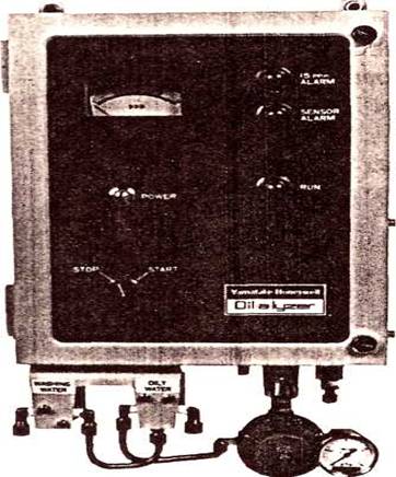
Fig. 1 "Oil-a-lyzer" Bilge Alarm
THEORY OF OPERATION
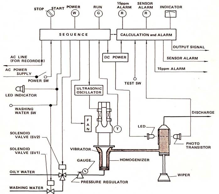
The measuring principle is based upon a turbidity method which detects the transmitted light strength through oily water containing dispersed oil drops. The oily water samples are flowing continuously and the samples are emulsified by the homogenizer at a certain fixed intervals. Then the transmitted light strength at each invervals are measured by art optical cell unit which is composed by a light emitting diode and a photo transistor.
Each data is compared to figure out the true oil content in a signal processing unit.
INSTALLATION
Install the instrument at safe place taking into consideration operability, maintainability, environmental condition, etc.
Note) To minimize sampling delay, mount the instrument on the place as closer as possible to a sampling point of an oil-water separator.
Mounting
The oil-a-lyzer is a wall-mount type with mounting holes (4—dia10) at the back of the cabinet.
Piping
The following three pipings shall be carried out:
(1) Piping for oily water sample
(2) Piping for washing water
(3) Piping for discharge
For each connection, ring joints of 8x6 copper tubes are supplied.
Sampling pipe
This is to introduce sample into the Bilge Alarm. Connect the pipe to the solenoid valve (SV2) for oily water.
Note: Take out samples from the center of a vertical pipe.
Washing water pipe
This is to introduce washing water (city water or sea water) into the Bilge Alarm to clean up the inside. Connect the pipe to the solenoid valve (SV1)
Discharge pipe
This is to discharge oily water and washing water. Connect the pipe to "OUTLET".
Note: The end of this pipe must be opened to the air, and must be lower than "OUTLET" position.
Wiring
For wiring, use wires with sufficient capacity. Wires for connection are as follows:
(1) Power supply,
(2) 15 ppm alarm,
(3) Sensor alarm signals,
(4) Remote start-stop (ON-OFF signals) in the case of the remote type,
(5) Output signals for recorder (indicator) and power supply.
The above must be carried out by use of cable glands. Screws for wiring terminals are M4 screws of the pressed lug type.
Power supply
The wiring should be good enough for consumption of approximately 200 VA.
Terminals are "8" and "9" on the terminal board TB— 1.
15 ppm alarm
The wiring is for use on an external alarm when oil content exceeds 15 ppm. Single pole and double throw (SPDT) contacts with capacity of 115V, 1A AC and 30V, 1A DC (resistive load) are provided on a normally energized relay. Terminals are "4", "5" and "6" on the terminal board TB—2.
Sensor alarm
This is also for use on an external alarm when the unit has become abnormal for some reason. Single pole and double throw (SPDT) contacts with capacity of 115V, 1A AC and 30V, 1A DC (resistive load) are provided on an normally energized relay. Terminals are "7", "8" and "9" on the terminal board TB-2.
Remote start
This is to get START-STOP signals (ON—OFF signals) from outside in case of the remote type. Terminals are "5" and "6" on the terminal board TB-3.
Recorder and power supply
The recorder (indicator) wiring is for output connection when it is separately provided.
Terminals are "7" and "8" on the terminal board TB—3.
However, power for the recorder is supplied by power supply unit in the bilge alarm unit to make the
same condition as that of monitoring of Bilge Alarm.
Terminals are "9" and "10" on the terminal board TB—3.
OPERATION
Start
(1) Check the "POWER" lamp. The lamp is on in a normal condition.
(2) When the "START-STOP" switch is turned to START position (ON signal from outside in case of the remote type), the "RUN" lamp goes on, the solenoid valve (SV2) for oily water opens and the measuring circuit is ready for immediate measuring.
Stop
When the "START-STOP" switch is turned to STOP position (Open-contact in case of the remote type), the "RUN" lamp goes off, the solenoid valve (SV2) for oily water closes, while the solenoid valve (SV1) for washing water is opened. The circuits stop to measure and monitor, allowing the flow-path to be washed up with washing water. The washing operation is stopped automatically after approximately 4 minutes.
NOTE: DO NOT OPERATE THE EQUIPMENT WITHOUT SAMPLE FLOW (PRESSURE INDICATION ZERO) FOR A LONG TIME.
MAINTENANCE
Calibration and Adjustment
Conduct operation in accordance with Section 6 (Operation). If operation is abnormal, perform the following procedures:
Check the installation, piping and wiring for abnormality. If any, correct faulty points.
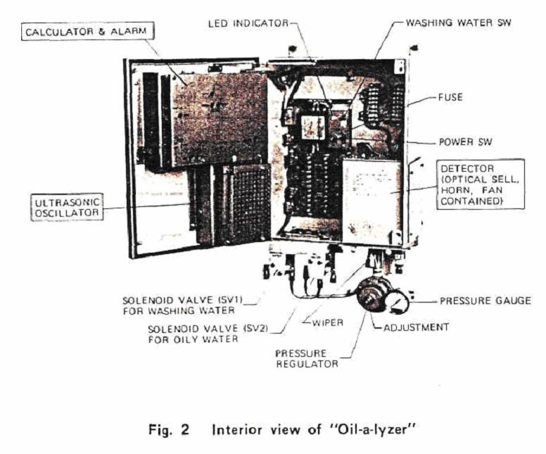
Check if the "POWER" switch inside the cabinet is on. When the switch is turned ON, the "POWER" lamp must be on, bringing it on a normal condition. This switch must always be set ON, except for servicing If the switch is turned off, both 15 ppm alarm and sensor alarm signals are generated to outside.
Clean inside the measuring device by moving the manual wiper up and down several times at the lower part of the unit. When the cleaning is completed, never fail to pull the wiper down.
When the wiper is remained upward, "SENSOR ALARM" lamp lights and an external alarm is generated to outside.
Check if the secondary pressure of the regulator is 0.2 kg/cm2. When the pressure is out of 0.2— 0.22 kg/cm2, first make sure the primary pressure is between 0.4-3 kg/cm2 , then adjust the secondary pressure with a pressure regulator.
When adjustment is required, loosen the lock nut of the pressure regulator to obtain the adjustment. Clockwise rotation makes the pressure increase.
After the adjustment, tighten the lock nut without fail.
Turn the "WASHING WATER" check switch ON, and "LED INDICATOR" lamp lights, causing the washing water solenoid valve (SV1) and the oily water solenoid valve (SV2) to be opened to wash the flow path of the bilge alarm.
In this case, set the "START-STOP" switch at STOP (open contact in case of the remote type). The "WASHING WATER" switch should normally be set at OFF.
Confirming "15 ppm ALARM"
When-the'TEST' switch is turned on during the time when the measur-ing circurt is in operation ("RUN" lamp is ON), an indication increases gradually to light "15 ppm ALARM" lamp, causing an external alarm to be
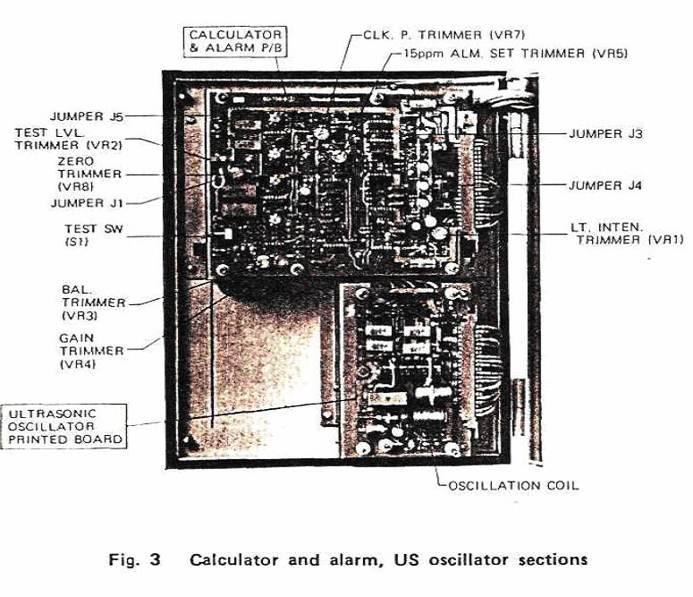
generated. The indication, however, stops at about 20 ppm. If not, first make sure the jumper J1 on the Computational section is connected to the pin 2 and J5 to the pin 1 and then turn the "TEST LVL" trimmer to obtain an indication of 20 ppm. After confirmation, set the 'TEST" switch to OFF without fail.
Confirming "SENSOR ALARM"
With the wiper remained in upward position, light from the photometry section is shielded and after approximately 15 seconds, "SENSOR ALARM" lamp lights to generate an external alarm signal. After confirmation, pull the wiper all the way down without fail.
Jumpers J3 in computational section
Jumper J3 is connected to pin 1 in general. However, connect it to pin 2 when the indication exceeds 15ppm frequently due to a sample condition, eventually causing the "15 ppm ALARM" lamp to be on.
• Connection to pin 1:
When the measured value exceeds 15 ppm, the "15 ppm ALARM" Lamp lights instantaneously to generate an external alarm signal. When it returns under 15 ppm, reset will be made instantaneously.
• Connection to pin 2:
When the measured value exceeds 15 ppm, the "15 ppm ALARM" lamp lights after 15 seconds to generate an external alarm signal. When it returns under 15 ppm, reset will be made instantaneously.
Zero adjustment
(1) Electrical checking and adjustment
• Electrical checking and adjustment can be carried out with the jumper J1 on the computational section connected to the pin 1 from the pin 2.
• Set the "TEST" switch to "ON" and confirm the indication of 0 ppm.
• If not, adjust it by the "ZERO" trimmer.
The J1 shall be connected to the pin 2 at normal condition.
(2) Temporary adjustment under on-line state
• To measure oil content in washing water (city water), set the "WASHING WATER" switch to "ON" and the "START-STOP" switch to "START" (closure contact in case of the remote type) with the jumper J4 on the calculator section printed board removed (both pins 1 and 2 are disconnected).
• Flow the city water enough to obtain stable condition and then the value at this time can be assumed to be a temporary zero.
• Adjust "ZERO" trimmer to obtain an indication of zero.
Note: NO READJUSTMENT IS REQUIRED AT SITE, because all instruments have been adjusted precisely in either case by city water at factory before shipment.
Sensitivity adjustment
(1) Adjustment in case that oil content is constant and its value is known. When a known oil content sample is flowing continuously, the indication value can be adjusted to the known oil content by the "GAIN" trimmer.
(2) Adjustment in case that oil content is varying
To adjust oil content to a value of a; sample at time of the pick, perform the following procedure:
1) Set the "TEST" switch at "ON".
2) Adjust the "TEST LVL" trimmer to obtain an indication of "R".
3) Then, adjust the "GAIN" trimmer to obtain an indication of "S".
4) Readjust the "TEST LVL" trimmer to obtain an indication of "20 ppm."
5) Set the "TEST" switch at "OFF".
Note:NO READJUSTMENT IS REQUIRED AT SITE, because all instruments have been calibrated exactly at factory before shipment by a reference oil complied with IMCO test.
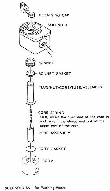
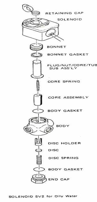
Cleaning solenoid valves
When solenoid valves become inoperative due to leaking or clogging for a long period of use, clean the valves according to the following procedure and the exploded view.
(1) Remove the solenoid from the plug-nut, core tube-subassemb-ly by moving the retaining cap.
(2) Remove the bonnet and pull out the core spring, core assembly and body gasket.
(3) For the oily water solenoid valve (SV2), further remove the end cover and pull out the body gasket, disc spring, disc and disc holder.
(4) Cleaning parts can be performed in the reverse of the assembling with care according to the exploded view.
Exploded View of Solenoid Valve
Checking
When the "SENSOR ALARM" lamp lights, check the following items:
"SENSOR ALARM" lamp will light when:
(1) Photometry section and computational section are degraded.
Abnormal contamination of the measuring cell is detected.
Abnormal heat up of the acoustic homogenizer is occurred.
How to clean parts:
(1) Clean the inside of the measuring cell by moving the wiper.
Be sure that the ambient temperature is not over 50°C.
Be sure that the outlet is not shut off.
Be sure that solenoid valves are not clogged with foreign materials.
Be sure that the cooling fan is not clogged with foreign materials.
Be sure that ultrasonic oscillation sounds at every four seconds.
