CAUTION
1. The device should not be installed at a dangerous place, where explosive or inflammable substance may be generated, accumulated, or stored.
2 . Using fire on the device for welding, ect, should be strictly prohibited to protcet the interal coatoating.
3. At the initial operation after the installation has finished or when the shells are empty after overhaul, be sure to fill the shells with clean seawater and keep it flow for more than ten minutes. After that bilge water may be processed.
4. Under automatic operation, the handle or solenoid valve should be turned anticlockwise to be always in "SHUT" position.
5. When the operation is started, the oil discharge valve and cock of the secondary column must be opened to drain oil.
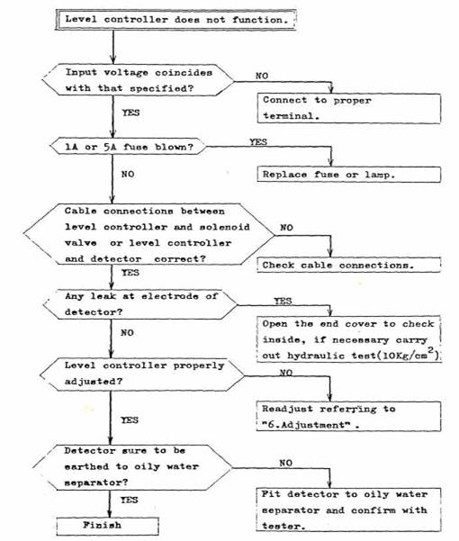
6. The electrode of level controller must be removed to clean and inspect at least once a month or whenever malfunction should occur.
7. When the oil content in effluent exceeds 15 ppm, it sometimes requires the replacement of filter element. The replacement should be carried out according to the manual for replacement.
8. Keep the primary and secondary columns be filled with seawater except when there is a risk of freezing or at the time of overhaul, cleaning and replacement of filter, element.
9. When the shells are drained, discharge the separated oil by the manual operation of solenoid valve in the primary column and by the operation of oil discharge valve and cock in the seconday column.
2. Structure .


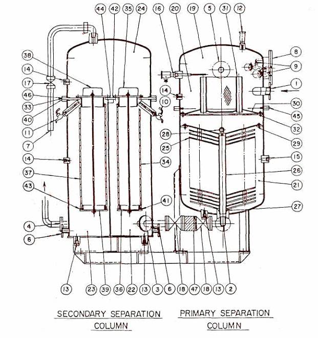
The TFU-(B) type Separating Tank comprises two vertical cylindrical columns - a primary separation column by the method of gravitational separation and a secondary separation column by the method of filtering or coalescing - and each column allows to divide into upper and lower halves.
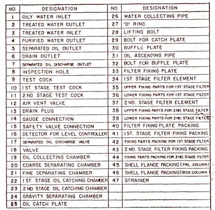
The primary separation column consists of an upper coarse separating chamber (20) and lower fine separating chamber (21) In the coarse separation chamber, there is an oily water inlet nozzle(l)fitted tangentially, and an oil collecting chamber (19) located at upper part is provided with a detector (l6) for detecting oil-water interface, an separated oil outlet nozzle(5), an air vent valve (12), etc. In the fine separating chamber, there are many oil catch plates (25)(conical plates) supported by a water collecting pipe (26)(vertical pipe), thereon the clearance between each catch plate forms a small separating chamber. The water collecting pipe located at center has water outlet holes at every small separating chamber, and its lowest end, treated water outlet(2), is connected to the inlet of the
secondary separation column by way of a strainer (47) and valves (18).
Between the coarse and fine separating chambers, a buffle plate (30) of conical form with an opening at its center and oil ascending pipes (3l) for oil being separated in the fine separating chamber are provided.
The secondary separation column consists of the first and second stage oil droplets catching chambers and a gravity separating chamber. At the lower part of the first stage oil droplets catching chamber, fitted is an treated water inlet(3)led from the primary column, while at the upper part a filter (34) for catching oil droplets.
In the gravity separating chamber (24), an oil collection chamber and an oil outlet are furnished. The second stage oil droplets catching chamber (23) has a filter(37) for catching oil droplets and, at the lower part, purified water outlet(4).
3. Function
Oily water fed from the pump for the separating tank (bilge feed pump) flows into the coarse separating chamber (20) through the oily water inlet(l)of the primary column and swirls slowly in the chamber tangentially. As a result, most of oil floats up to the oil collecting chamber (19) .
Then, oily water enters the fine separating chamber (21) through a central opening on the buffle plate (30) , and flows from the circumference to the water collecting pipe (26) through clearances between oil catch plates (25). In the course of this process, oil floats and adheres to the reverse side of each catch plate, and it is separated from water.
After this separation, water passes small holes on the water collecting pipe and goes to the secondary separation column by way of treated water outlet (2).
On the other hand, oil adhered to catch plates accumulates increasing its buoyancy and gradually moves toward the plate circumferences. Then, it leaves the edge of each plate forming oil globules. As these are large in size and in floating velocity, they can easily float up to a buffle plate against down-flow of oily water and finally into the oil collecting chamber (19) through two oil ascending pipes (31).
The amount of oil in the collecting chamber is perceived by the detector (16) of the automatic oil level controller. When the amount exceeds a limit, the solenoid valve at the separated oil outlet(5)is energized automatically to open by a signal given from the electrode and discharges oil. The valve closes automatically after a preset while by a timer mounted in the controller.
A certain amount of air over-carried in influx from the pump retains at the top of primary column in order to form an surge chamber, which cancels fluctuation or pulsation given by the pump and the excessive air is automatically discharged through the air vent valve (12) .
The above method of separation is a so-called gravitational separation utilizing the difference of specific gravity between oil and water. However, by this method, it is difficult to eliminate fine oil droplets, or suspended solids whose specific gravity is similar to water. As a gravity separator, the primary separation column has a high efficiency, but still fine oil droplets or suspended solids are contained in the effluent. The fine oil droplets are eliminated in the secondary column while the others are removed by the strainer (47) at the outlet of the primary column, which will prevent possible clogging of filter element.
Oily water led to the secondary column goes through the first stage filter element (34) at first, where the most fine oil droplets are filtered. By passing through the second stage filter element (37), those extremely fine oil droplets that could not be caught in the first stage filter are removed and the purified water is discharged overboard through the purified water outlet(4).
Meanwhile, the oil droplets caught in the first stage filter coalesce together to form large globules and float up to the oil collection chamber at the top of gravity separating chamber(24).
Since most oil has been removed in the primary separation column, the oil amount collected in each oil collection chamber is very little under a normal operation. Therefore, it is enough to open the separated oil discharge valve (17) by hand once a month periodically, but the valve is recommended to be opened to discharge oil in oil collection chamber at every start-up of operation to avoid the negligence of operating this valve. Cock (10)(11) at the top of each stage oil catch chamber should also be opened at the start-up.
4. Piping
Carry out piping work referring to the "PIPING ARRANGEMENT".
5.
Operation (See the "PIPING ARRANGEMENT")
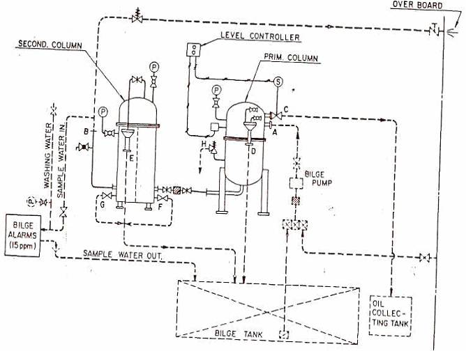
Specially complicated or difficult works are not needed for the TFU-(B) type oily water separator. At first, before putting into service, confirm that the piping system are laid as per the attached "PIPING ARRANGEMENT" and the cable connections for automatic oil level controller are correct.
After the confirmation has finished, carry out the operation according to the following procedures.
5-1. Filling Seawater into Separating Tank
(1) Open all valves on seawater line from seawater intake through pump's suction to fill suction line with seawater.
(2) Open all valves on the piping from the pump to separating tank and from separating tank to overboard discharge port.
(3) Fully open the valves positioned between the primary and secondary separation columns.
(4) Open the separated oil discharge valve at the upper part of the secondary separation column.
(5) Turn the handle at the upper part of solenoid valve counterclockwise to its stop and set the valve to "SHUT" position.
(6) Confirm the power source lamp is alight when the power switch of automatic level controller is set to "ON".
(The oil discharge lamp on the level controller lights and the solenoid valve closes automatically when the level in the primary separation column is lower than the position of lower test cock and the electrode is in air.)
(7) Start the pump to flow seawater in the separating tank.
(8) Close the separated oil discharge valve of the secondary separation column after seawater has been confirmed to flow out from the valve.
(9) Let seawater flow for more than 10 minutes after seawater has been observed to flow out from the upper test cock of the primary separation column. Stop the pump after that.
Above procedures complete the work to fill the separation tank with seawater.
5-2. Start-up (Carry out the operation of separating tank according to the following procedures .)
(1) Close valves of the seawater line on the pump's suction side.
(2) Open all valves on the bilge suction line from the bilge tank to pump.
(3) Select the switch of the automatic oil level controller to "ON". Confirm the source lamp will light.
(4) Start the bilge feed pump to feed bilge to the separating tank.
(5) Adjust the pressure regulating valve to set the pressure in the primary separation column within 0.5 - 2.0 Kg/cm2 . The set value of the pressure regulating valve should be lowered depending upon the increase of pressurg loss in the secondary column when the filter becomes dirty
Upon completion of above procedures, oil-water separation of bilge and the overboard discharge of processed water will begin.
5-3. Discharge of Separated Oil
The separated oil in the separating tank stays in the oil collecting chambers at the top of the columns. In the primary separation column, this oil is automatically discharged by the automatic oil level controller when the oil amount exceeds the determined level. If the automatic oil level controller will not work despite the fact that separated oil flows out from the lower test cock, check and adjust the controller according to "Instruction Manual for Automatic Oil Level Controller" .
However, in case the controller and solenoid valve should not function by any means, carry out the manual operation as follows:-
1) Open the lower test cock occasionally. if oil runs from the cock, discharge oil in the oil collecting chamber by turning the handle at the upper part of solenoid valve clockwise to open it. Then open the upper test cock. When water begins to run from the cock, shut the solenoid valve by turning the handle counterclockwise.
(Note) Special care should be taken under manual operation not to allow excessive oil accumulation. Frequent check to assure the oil amount by opening the lower test cock is necessary during the manual operation.
2) The position of upper test cock has been determined especially for manual operation. The level is different from that of closing solenoid valve by the timer of automatic oil level controller.
3) Under the normal automatic operation, the handle of solenoid valve must always be turned counterclockwise.
Regarding the secondary separation column, it takes a long time to collect a certain amount of oil in the oil collecting chamber because most oil has been separated in the primary column and very little amount of oil is separated in this column. Therefore, it is sufficient to open the oil discharge valve by hand periodically once, a month under the normal operating condition. But the valve is recommended to be opened to discharge oil in the oil collecting chamber at every start-up in order to avoid the negligence of operating this valve. Also, test cocks at the upper part of the first and second stage oil catch chambers should be opened.
5-4 . Stop of Operation
(1) When the discharge work of bilge is finished, flow seawater for more than 10 minutes in order to prevent the change in quality of oily mixture remaining in the separating tank while the suspension.
(2) Stop the bilge feed pump and close all the valves on the bilge discharge pipe line.
(3) Turn off the switch on the automatic oil level controller .
Now, the operation of separating tank has been stopped. When the operation is restarted, fully open all the valves on the bilge discharge pipe line and start the pump. It is not necessary to fill seawater as mentioned in 5-1 except when the separating tank is drained out for overhaul etc. since the tank has been kept full.
.
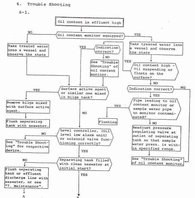
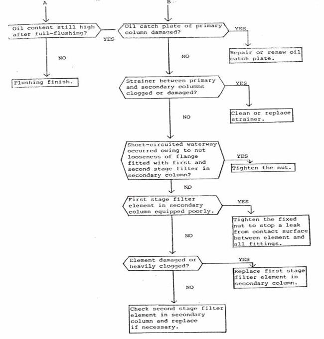
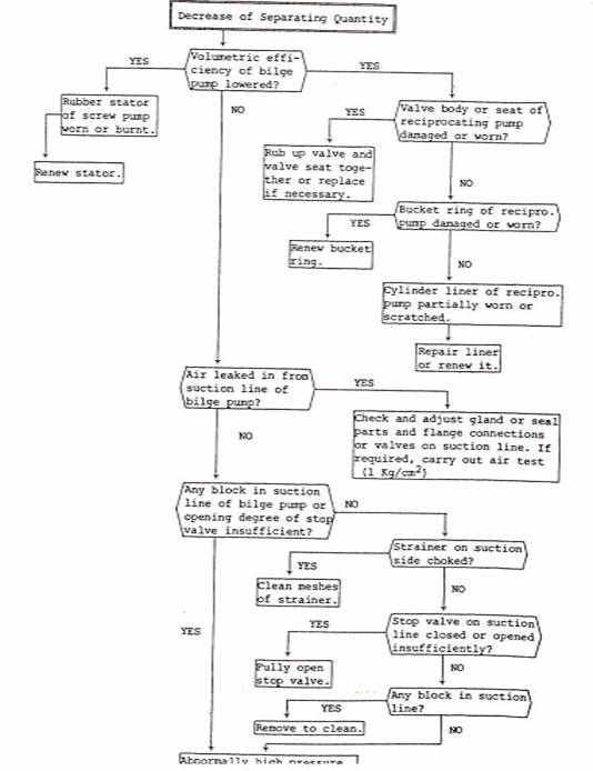
7. Maintenance
Carry out the following maintenance work periodically and clean the strainer (47) between primary and secondary columns whenever overhaul or cleaning the separator, or as occasion demands.
7-1. Overhaul and Cleaning of Primary Separation Column
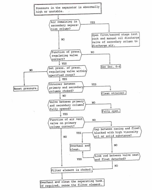
Under normal condition, once or twice a year interval will be enough for the overhaul and cleaning of the primary separation column. However, if the pressure in the column should rise extremely no matter how normal operation is maintained according to this manual, foreign substances such as sludge may be accumulated over the catch plates and water collecting pipe. In this case, the separator must be cleaned immediately.
The overhaul and cleaning of the primary separation column is as follows:-
Separated oil in the oil catching chambers (22)(23) and at the top parts of separating tank (l9)(24) should be
discharged at first as much as possible according to following procedures.
(1) Switchover the suction line of pump from bilge to seawater side.
(2) Start the pump.
(3) Turn the handle of solenoid valve clockwise to open manually.
(4) Open the oil discharge valve and test cocks at the upper parts of first and second stage oil droplets catching chambers to drain oil in the secondary separation column and close when all oil is drained.
(5) Stop the pump after about one minute since seawater begins to run out" from the upper test cock of the primary separation column. Then keep ing tank for 5-10 minutes as it is.
Now, the separated oil in both columns has been discharged. Carry out overhaul and cleaning as follows:-
(6) Close valves on the oily water inlet and purified water outlet line.
(7) Switch off the automatic oil level controller.
(8) Drain water from the drain outlet (l3) of the primary separation column and from drain valve on the first stage side of the secondary separation column.
(9) Remove the pipes and wirings connected to the upper shell.
(10) Remove bolts at shell flange and dismantle the upper shell.
(11) Check and clean the electrode. (If necessary, remove it. Turn the hexagon nut with a spanner.)
(12) Remove bolts (32) fitting the buffle plate (30) and detach the plate.
(13) Remove three bolts (29) for fitting catch plates. Loosen the bolt of retaining plate and turn it inside.
(14) Lifting eye bolt (28) , take out the catch plates (25) and water collecting pipe (26) as a complete set.
(15) Take away the lifting bolu(28) and pull out the catch plates (25) one by one from the water collecting pipe (26). Disassmble catch plates taking the order of reassembling into consideration.
(16) Check and clean catch plates and the water collecting pipe.
(17) Clean the inside of shell and check if there is any damage on coating. Should the peeling of coating, etc. be observed, repair it according to the section 7-3 Preservation and Inspection of Internal Coating.
Steam or hot water (above 60°C) must not be used for cleaning.
(18) Reassemble to the former state taking care so that the holes of water collecting pipe are placed almost at the center between catch plates.
(19) Restore in the reverse procedures of overhaul. In assembling, renew the shell flange packing (45) and "0" ring (27) for water collecting pipe. Also, the handle of solenoid valve must be turned counterclockwise to shut.
7-2. Overhaul of Secondary Separation Column and Replacement of Filter Element
Renew the filter, when the oil content in effluent exceeds 15 ppm owing to damages or clogs of filter elements. However, there are some cases that the oil content exceeds 15 ppm, when oil content of bilge is corpuscular according to the intermixture of chemicals, for example, surface active agent and etc., when oil grains are minuted because accumulative efficiency of bilge pump falls, and when polluted goods adhere or accumulate on the inside of oily bilge separator. Therefore, it is necessary to confirm whether oil content is under 15 ppm after checking and consolidating filter elements or taking measures to prevent that oil content exceeds 15 ppm, before renewing the elements.
Enforce the overhaul of secondary separation column and the replacement of filter elements according to the following precedure. First, discharge the separated" oil in the primary and secondary separation columns as much as possilbe before stopping the operation in accordance with the aforementioned section 7-1, (l)-(5).
procedure of Overhaul and Assembly:
(1) Close the isolation valve (18) between primary and secondary separation columns.
(2) Open the drain valve in the bottom of primary and secondary oil droplets catch chamber and drain water.
(3) Remove the bolts of shell flange and take out the upper shell.
(4) Unscrew the nuts of the flange fitted with filter (34) or (37) and pull out the filter.
(5) Remove adhesives completely in the inner surface of column, the upper and lower fixing parts of element, and the inside of purified water outlet. Further, clean with water and check if there is any damage. If there are damages such as the peeling of coating and etc., repair those parts according to the section 7-3 "Preservation and Inspection of Internal Coating". Steam or hot water (about 60 °C) and such should not be used for cleaning.
(6) When filter elements are to be renewed, remove the elements from the retainer and replace with a new one after taking out the stick nuts fixing the filter.
(7) Renew the packings (41)(43) to fit filter elements when the elements are replaced.
(8) Give a careful attention to fit filter elements, especially so that there may not happen the leak in the contact surface between the elements and the retainer.
(9) Restore in the reverse procedure of overhaul. If necessary, renew the shell flange packing.
(10) Operate the bilge pump and make clean sea water flow for about ten minutes after opening the isolating valve, when the restoration of the separation is finished.
Operation must be conducted according to the procedure of section 5-1, when it is finished to open the secondary separation column and replace filter elements by the above precedure.
7-3. Preservation and Inspection of Internal Coating
The inside surface of primary and secondary separation columns is applied with tar epoxy coating in order to prevent corrosion.
Overhaul and check once a year or so if there is any damage on the coating.
(1) Overhaul and Inspection of Primary Separation Column Carry out the overhaul and inspection according to the section 7-1 "Overhaul and Cleaning of Primary Separation Column" and, in case of damage of coating is found out, repair according to item (3) of this section.
(2) Overhaul and Inspection of Secondary Separation Column
Remove the first and second stage filters according to the section 7-2 "Overhaul of Secondary Separation Column and Replacement of Filter Element". Check the inside of the first and second stage oil droplets catching chambers through the hole of fitting filter. If further check or repair work should be required, remove the bolt at the center of filter Fixing plate (33) and bolts around the plate, and detach the filter retaining plate. Repair in accordance with item(3), when damage of coating is found out.
(3) Repairing Procedure of Coating
Material for repair : Tar Epoxy Resin Repairing Procedure:
a) Clean the surface where coating peels off with a hand grinder, a wire brush, etc. to remove stains such as rust.
b) Wipe off oil with gasoline, trichloroethylene, etc.
c) Dry completely with an electric bulb, etc.
d) Mix tar epoxy resin : Refer to the instruction manual of the manufacturer since the blending ratio of hardner and principal compound differs depending on each manufacturer.
e) Paint the mixed tar epoxy resin with a brush. Apply the second coat if primary coat does not adhere to a finger. Apply at least three times in the same manner.
f) Dry the coating with an electric bulb, etc. after painting has finished.
g) Restore if traces pressed down by nailes do not remain on the coating. It is desirable not to feed water to the separator within one week as much as possible, because it takes more than one week for the coating to harden completely.
2. NOTES FOR INSTALLATION
General
The level controller shall be equipped for the oily water separator and, in combination with the solenoid valve, used for the automatic operation (automatic oil draining) of the oily water separator.
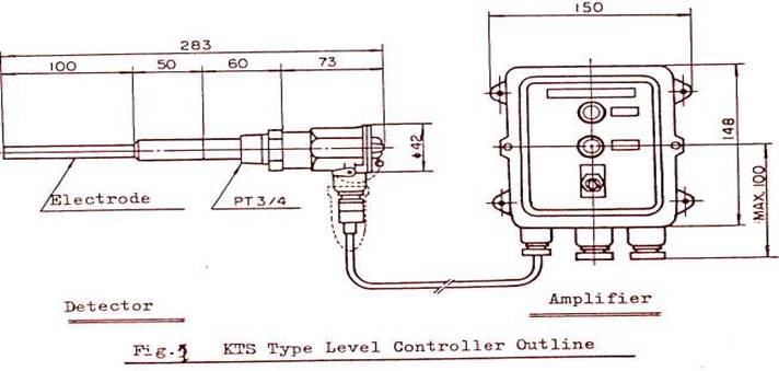
As shown in Fig.l, the KTS type level controller is composed of the detector, amplifier and high frequency cable interconnecting these two devices.
Principle of Operation
The level controller forms a kind of condenser between the electrode and inside surface of the oily water separator shell.
The capacitance of this condenser will change in proportion with the dielectric constant of the measured object which presents between the electrode and inner wall surface of the oily water separator shell. The level controller detects and controls the interface sensing the capacitance which varies depending upon the kind of measured object. The detector is fitted to the lowest level in the control range of the
oil-water interface.
For example, when the oil-water interface reaches the lowest level, the detector transmits a signal to the amplifier at the same time and operates the solenoid valve.
Thus, the level controller serves to control the oil-water interface to keep it always above the lowest level.
The solenoid valve is energized to open(relay-off) when the electrode is in oil and close(relay-on) when in water. In case the electrode part changes to water from oil, the solenoid valve goes to the close position (relay-on) after maintaining the open position(relay-off) for a preset while by a electronic timer circuit. On the other hand, in case the electrode part changes to oil from water, the closed solenoid valve(relay -on) will open(relay-off) after 2-3 seconds by the circuit to prevent chattering.
Detector Amplifier

Fig. 2 Block Diagram
A : Tuning Circuit
B : High Frequeency Power Source.
C : Stabilized Power Source
D : Signal Detecting Circuit
E : Timer & Chattering Prevention Circuit
F : Output Relay ( Live Contact)
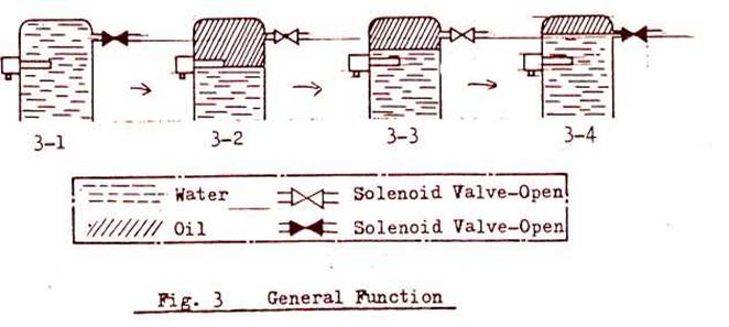
a. Fig.3-1 : Solenoid valve opens. b. Fig.3-2 : Solenoid valve closes. c. Fig.3-3 : Electronic timer is brought in the circuit to keep solenoid valve open for preset time. d. Fig.3-4 : Solenoid valve closes (after the preset time of electronic timer is set up).
Installation and wiring (Normally, installation work for level controller and solenoid valve and wiring for these have been done at our shop.)
(1) Screw the hexagon gland of detector to the oily water separator with a spanner.
(Do not force to turn the detector body.)
(2) Upon completion of fitting the detector and amplifier, connect the detector and amplifier with the high frequency cable.
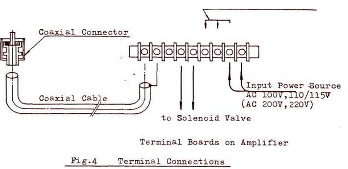
At the amplifier side, connect the cable core to the (+), terminal and the shielding braid to E terminal. At the detector side, use
the connector.
(3) Connect the jumper wire according to the input source value.
Jumper Wire
Operation
(1) After the detector and amplifier have been installed on the oily water separator, these devices are interconnected with the high frequency cable and the wiring work to AC power source and the solenoid valve iB finished according to the procedures described above; Now, the unit is ready to serve without any adjustment.
(2) At the "ON" position of power switch, the white pilot lamp on the amplifier will light, and at the "OPEN" position of the solenoid valve, the green lamp on the amplifier will be alight.
6. Adjustment
As the unit has been adjusted precisely to assure the correct function for the oily water separator prior to shipping from our shop, it is not necessary to readjust further. However, if the set point should get out of position due to an impact given to the detector or amplifier, or if the dielectric constant should change due to the accumulation of adhesives to the wall surface of the oily water separator shell and electrode, the solenoid valve may not always function correctly. If such cases should occur, readjust it as shown below.
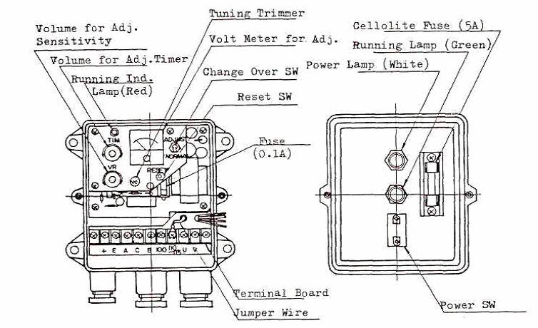
Fig. 5 Inside Arrangement of Amplifier
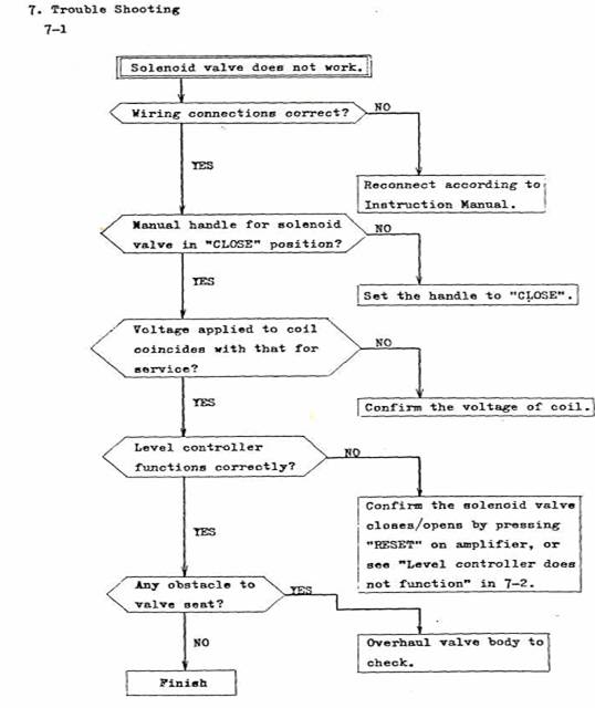
(1) Discharge the separated oil remaining inside referring to the items 7.l(l)-(5) of "Instruction Manual for Oily water Separator".
(2) Lot the level in the primary column down lower than the lowest level (the position of test cock at the lower part).
(3) Turn on the power switch and set the electronic timer (2) to the smallest. (Turn the VR for adjusting timer to left to its stop.)
(4) Select the change over switch to "ADJUST" side.
(5) Turn the tuning trimmer (4) either to right or left to make the voltage indication on the volt meter for adjustment smallest. (Since the tuning point in hard to get when the reading of volt meter comes to nearly zero, adjust it after the voltage indication is raised to 2-4V by turning the VR ,(3) for adjusting sensitivity to right.)
(6) Turn the VR (3) for adjusting sensitivity to confirm the relay is energized to on when the On/Off signal lamp for relay is alight at around 5V shown on the volt meter for adjustment. (Note) Turn the VR for adjusting sensitivity slowly as the delay-timer has been set in.
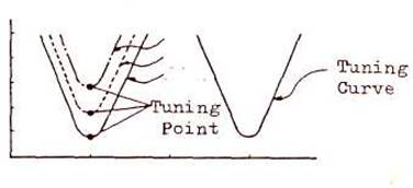
(Note) By turning the volume for adjusting sensitivity the tuning point will give vertical move as shown by the curves A, B and C.
(7) Select the change over switch to measuring side.
(8) Set the voltage on volt meter for adjustment to 2V by turning the VR for adjusting sensitivity.
(Note) Water content in the separated discharge oil can be changed by adjusting the VR to determine the set voltage of sensitivity .
Set voltage above 2V ... water content will decrease.
Set voltage below 2V ... water content will increase.
(9) Confirm the solenoid valve will open/close (relay : ON/OFF) at the determined interface when the level in the oily water separator goes up or down.
(10) Set the electronic timer (2) to maximum. (Turn the VR for adjusting timer to right to its stop.)
Now the adjustment has been completed.
