INSTRUCTION FOR FRESH WATER GENERATOR
CAUTION
1. Making fire for welding and so on should be prohibited for fear that it destroys inside coating of the plant.
2. The following-mentioned should be obeyed strictly to check out corrosion of both tube plate and cooling tube for condenser.
a) At starting of plant, air inside the cover for condenser should be exhausted without fail by opening the air-vent valve.
During operation, the valve should be opened at a proper time to prevent collection of bubble inside the cover.
(If possible, it is advisable that the valve is open little during operation.)
b) Cooling sea water inlet valve of condenser during operation shall be fully open and cooling sea water quantity
must be controlled by outlet valve to keep constantly back pressure of about 0.2 kg/cm2 G. at the lowest.
c) Cooling sea water shall be throttled at outlet valve lest the difference of temperature between cooling sea water at outlet and inlet" is less than 4 °C and 6 °C.
d) Observe Anode Protectors installed in Condenser Cover about every six months concerning their installation condition and their exhaustion degree.
When their exhaustion is remarkable, exhange for new ones.
1. GENERAL DESCRIPTION
This fresh water generator has enough capability to supply drinking water, boiler feed water and water for miscellaneous uses. This equipment reduces the space occupied by the fresh water tank and increases that for cargo. It is useful for increasing profit.
2. DESCRIPTION OF THE PLANT
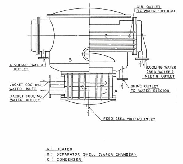
The Fresh Water Generator consists of heat exchanger, separator shell and condenser. And the water ejector for air, the water ejector for brine, the ejector pump, the Distillate pump, the electrical salinity indicator, the solenoid valve, and the water meter are supplied as the attachments.
3. FEATURES OF THE PLANT AND ITS OPERATION
Since the Fresh Water Generator utilizes the waste heat in the circulating cooling water from the diesel engine, no fuel expense is required. The energy requirement for operation is only electricity to be used for the power to accessory pumps. In case of damage to the fresh water cooler, it will in many cases be possible to use the fresh water generator only as cooler during the repair of the fresh water cooler. Diesel engine circulating cooling water normally has a temperature of about 65° to 80°C (149° - 176°F) at the outlet of the diesel engine, and part of the cooling water is led to the heat exchange in the fresh water generator where it circulates on the outside of the heating tubes, giving off heat to the sea water passing through the tubes.
The sea water then evaporates at a temperature of 35° - 50°C (95° - 122°F) because the inside of the generator is formed vacuum by the water ejector. The vapor produced in the heat exchanger passes through the deflector and mesh separator (where possible entrained water drops are separated) to the condenser where it is condensed by the sea cooling water which passes through the condenser inside the tubes.
The water Ejector for air is connected to the condenser shell and takes out air and non-condensible gasses so that inside of the Fresh Water Generator can maintain the high vacuum which stipulates the low evaporation temperature of 35° to 50°C (95° - 122°F).
The water ejector for brine takes out from the brine outlet of the separator shell the salt water which is not evaporated in the heat exchanger and discharges it constantly out of the board.
The ejector pump is a motor driving horizontal single suction centrifugal pump which not only admits service sea water to the above mentioned air ejector and to the brine ejector, but also supplied feed water to the shell.
The distaillate pump is likewise a motor driving horizontal single suction centrifugal pump which extracts the fresh water produced from the condenser of the Fresh Water Generator and transfer it to the fresh water tanks of the vessel.
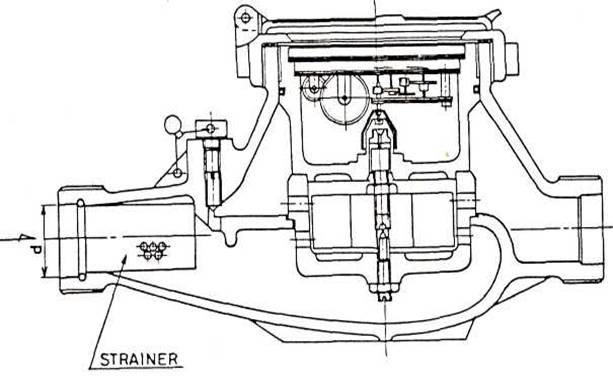
Feed water supplied by the ejector pump flow into the bottom cover of the heat exchanger after passing through a strainer, a spring loaded valve, and the feed water orifice.
4. CONSTRUCTION OF THE PLANT AND ITS MATERIALS '
1) Heat Exchanger
Heating tube buncfle consists of strainght aluminum brass tubes, expanded into a tube plate of neval brass at each end. The heat exchanger shell is made of steel plate and the upper flange of the shell is bolted to the lower flange of the separator shell together with the upper tube plate.
The bottom cover of the heat exchanger is made of the steel plate and coated internally with neoprene.
2) Separator Shell and Condenser
The separator shell is vertical and cylindrical type of steel plate coated internally with neoprene, and it has a deflector (a baffle plate separating vapor and water) of glass fiber in the bottom part, a condenser in the upper part, and mesh separator of stainless wire in the medium part. The condenser consists of the shell of stainless steel, the cooling tube bundle of aluminum brass tubes, tube plates of naval brass and the cover of cast iron or steel plate internally coated with neoprene.
The upper cover of the separator shell is of steel plate and coated internally with dimetcote.
3) Water Ejectors
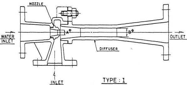
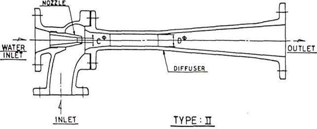
The water ejectro for air and that for brine consist of the suction chambers and the difuser of cast bronze and the nozzles of stainless steel.
4) Ejector Pump & Distillate Pump
As to the ejector pump, its casing is of cast bronze, impeller is of phosphor bronze or stainless steel casting and shafts are of stainless steel. As to the distillate pump, its casing is of cast iron, impeller is of phosphor bronze and shafts are of stainless steel.
5. STARTING UP
Before starting, the following valves are to be closed.
Inlet and outlet valves for jacket cooling water of heat exchanger
Vacuum breaker valve
Outlet valve for distillate pump
Feed water inlet valve of heat exchanger
Bottom blow valve
1) Start the ejector pump and then open the pump outlet valve and the overboard discharge valve.
2) Open sea cooling water inlet and outlet valves of the condenser.
3) Open the air outlet valve to ascertain that the cooling tube of the condenser are filled up with water and after the air is discharged completely close the valve. If possible this valve is preferable to be slightly open during operation.
4) Open the feed water valve and let sea water in t.o the heat exchanger. Feed water quantity can be seen by the readings of the compound gauge in front of the feed water orifice. Control feed water quantity within range of green belt (1.2 - 1.8 kg/cm2) shown in the compound gauge.
Regarding the relation between feed water quantity and feed water pressure, please refer to the attached drawing.
5) When the vacuum within the generator becomes about 70 cmHg, open the inlet and outlet valves for jacket cooling water of the heat exchanger. The outlet valve for jacket cooling water is to be opened slowly lest the heat exchanger should be overheated suddenly.
6) The air vent cock at the upper part of the heat exchanger shell should be opened whenever jacket cooling water passes through the heat exchanger and should be closed after confirming that the air in the shell is completely discharged.
7) When the distillated fresh water comes up to the level gauge of the suction pipe of distillate pump, start the distillate pump and regulate the water quantity by the outlet valve of the pump.
The water level is desirable to be kept to the fixed point. However, if there is not abnormality on the discharge pressure of distillate pump , the level need not always be fixed, provided that the level gauge is not filled. Because, it means that the condenser is filled with fresh water and it decreases the cooling area of the condenser.
8) Work the electrical salinity indicator in order to check purity of the fresh water.
Notices:
1) In the beginning of the water supply after starting up the ejector pump, confirm that the reading of the feed water compound gauge on the instrument panel indicates within the green belt under the condition of full opening of the feed water valve. In case that this feed water pressure does not reach the prescribed value, a clog of the strainer, pressure regulating valve's not being adjusted or the dry-running of the ejector pump is considered as a cause.
2) A feed water orifice is provided in order to automatically feed the sea water of three to four times as much as the distillate to the heat exchanger, when vacuum in the shell reaches about 70 cmHg.
3) In case of opening the outlet valve for jacket cooling water, open said valve gradually, watching the evaporating condition tnrouqh the sight glass so as not to begin excessive boiling.
4) In case that the temperature within the shell falls at about 35°C (95°F) and below, regulate the temperature to stand at about 35°C to 45 C (95°C to 113°F) by decreasing the quantity of condenser cooling sea water or by opening the vacuum breaker valve slightly.
5) In case that the inlet temperature of the jacket cooling water is lower than the prescribed one, increase the quantity of the jacket cooling water which passes through the heat exchanger.
6) If the outlet pressure of the pump does not reach the prescribed one after starting up the distillate pump, stop it at once because there is a fear of the dryrunning of the pump.
7) The regulation of the quantity of the jacket cooling water shall be done by the outlet valve of the heat exchanger in order to assure the heat exchanger to be always filled with jacket cooling water.
6. REGULATING THE CAPACITY
The capacity (quantity of produced water) of the Fresh Water Generator is regulated by increasing or decreasing the quantities of jacket cooling water to the heat exchanger.
The capacity of the plant is now measured by means of the water meter, the quantity of the jacket cooling water shall be regulated by the by-pass valve to the fresh water cooler until the plant yields its normal capacity.
In case of operation at rated capacity, temperature of the jacket cooling water is to fall usually about 5° - 10°C by passing through the heat exchanger.
In case that the temperature of the jacket cooling water is lower than the prescribed one, the flow quantity passing through the heat exchanger shall be increased more.
The supply of cooling sea water to the condenser is regulated so that the cooling sea water temperature rises about 5 C (9 F) when passing through the cooling tubes of the condenser.
The evaporation temperature should be about 35 to 5O°C (95° - 122°F). If the evaporation temperature is too low which may occur at low sea water temperature area, the vacuum breaker valve is opened little or the quantity of the cooling sea water for the condenser is decreased which will make the evaporation temperature rise. If the evaporation temperature is too high which may occur at high cooling sea water temperature, the quantity of cooling sea water to the condenser is increased which will make the evaporation temperature sink.
Too high evaporation temperatures increase the risk of scale formation in the tubes of the heat exchanger, and too low evaporation temperature will o'wing to the resulting great vapour volumes mean a risk that sea water drops are brought with to the condenser resulting in fresh water with a too high salt content.
7. STOPPING
When the vessel approaches a port, land or estuary the Fresh Water Generator is desirable to be stopped because at such places the sea water may be heavily infected with bacteria, and there is a risk that bacteria can be transferred to the fresh water produced. Consequently, care should be taken in time that there is sufficient fresh water in the tanks of the vessel for use during the stay in port. Before the Fresh water Generator is stopped the by-pass valve for the jacket cooling water should first be opened and thereafter the inlet and outlet valves of the heat exchanger should be closed. By closing the said inlet and outlet valves, evaporation of the sea water in the
heat exchanger will now diminish and gradually come to a standstill due to lack of heat.
Next the distillate pump should be stopped and the outlet valve of that pump should be closed. Thereafter the ejector pump is stopped and the vacuum breaker valve is opened.
After the ejector pump is stopped, the feed water valve is closed and the suction valve of the pump and the overboard discharge valve of the water ejector are closed.
In case that the plant is stopped for a long time, the heat exchanger is emptied of sea water by opening the bottom blowoff valve at the bottom of the heat exchanger. Finally the by-pass valve for cooling sea water is opened, and the inlet and outlet valves of the condenser are closed.
Note
No jacket cooling water should be circuited through the heat exchanger during period when the Fresh Water Generator is not in operation as this can cause scale formation in the tubes/if the heat exchanger has not been emptied of sea water. Nor should cooling sea water be circulated through the condenser when the ship is in an estuary, near land, and in harbour as this may result in clogging up the condenser tubes with impurities from the sea water.
8. ATTENTION DURING OPERATION
The risk of precipitation of salt content in fresh water produced in the Fresh Water Generator is extremely small if the evaporation takes place at a temperature of 35° - 50°C (95° - 122°F), and therefore, the evaporation temperature should always be kept within these limits.
1) Regulating the Capacity
Any regulation of the capacity of the Fresh Water Generator should be effected by regulating the admission of jacket cooling water to the heat exchanger as mentioned above and not for instance by artificially reducing the vacuum by letting air into the Fresh Water Generator or by admitting a small quantity of sea cooling water to the condenser.
Regulation of the amount of jacket cooling water to the heat exchanger should be effected by the by-pass valve or the valve before the fresh water cooler if the Fresh Water Generator is connected in Parallel with the fresh water cooler.
The difference in temperature between inlet and outlet of the jacket cooling water in the heat exchanger depends on the capacity of the generator, the evaporation temperature and the inlet temperature of jacket cooling water. At the rated capacity, 65° - 80°C (149° - 176°F) jacket cooling water temperature and 35° - 5O°C (95 - 122°F) evaporation temperature, the fall in temperature of the jacket cooling water in the heat exchanger will be about 8° C (14 F).
Although when the tubes are clean, the Fresh Water Generator will be able to produce fresh water in excess of its rated capacity, we recommend that you will operate the plant at the prescribed quantity of fresh water or less as production in excess hereof can involve the risk of scale formations.
2) The Condenser
In order to make sure of condensing all vapor generated in the heat exchanger, as cold cooling sea water as possible should be flow to the condenser. Generally, the quantity of the cooling water shall be sufficient to give a rise in the temperature of about 5 C (9 F) in passing through the condenser. When the sea water temperature is about 30 C (86 F) and over, more sea water should be led to the condenser and consequently the plant should sometimes be operated at a rise in temperature of about 3° - 4°C. In this case, however, care should be taken because the pressure drop through the condenser will of course rise by supply of ample sea cooiing water and there will be the risk of turbulent corrosion in the tubes with too high velocities of the water in the condenser tubes.
Consequently we recommend to run the plant with reduced capacity when a high sea water temperature makes it difficult even with the stated increase of the cooling water amount to keep the evaporation temperature below 5O°C (122°F).
During operation the condenser should contain no fresh water in order to obtain the largest possible cooling surface in the condenser.
3) Amounts .of Cooling Water through The Heat Exchanger and Condenser
The normal amounts of jacket cooling water at a temperature of 65 C (149°F) and a cooling sea water temperature of 3O°C (86°F). for the various types of Fresh Water Generators can be seen from the following scheme:
During operation, the amounts of water can be controlled by the following formulas:
Jacket cooling water : a x 600\ t2- t1m3 /h
Cooling sea water : a x 600\ t2- t1m3/h
where "a" indicates the amount of fresh water produced in m3 /h, and "t2-t1" the difference of temperature in °C of the jacket water supplied.
4) The Pumps
Distillate pump is easy to cause flashing or cavitation because suction vacuum of the pump is high and suction water has a saturated temperature. The discharge valve of the pump should be opened properly because if the impellers of the centrifugal pump are not always given water resistance, the above-mentioned phenomenon
occurs frequently. When the pump causes cavitation, the pressure gauge at the discharge side indicates "0" at the same time that the strange sounds are made in the casing. In such a case, the discharge valve should be closed perfectly and remained until the pressure gauge indicates the initial pressure of the pump, then thereafter the valve should be opened gradually.
If the cavitation is not removed even applying the above method, the pipe line should be inspected.
The dry running of both of the ejector pump and the distillate pump should absolutely be avoided.
5) Salt Content in the Fresh Water Produced
If the Fresh Water Generator runs normally without overproducing or too low evaporation temperature, there should be no risk of a too high salt content in the fresh water produced. Usually the salt content of the fresh water produced is below 10 mg per litre (10 p.p.m.).
6) Automatic Control of the Salt Content in the Fresh Water
The Fresh Water Generator is furnished a salinity indicator which automatically registers the salt content in the fresh water produced.
This salinity indicator gives an alarm if the sea-salt content exceeds 10 mg per litre (10 p.p.m.). In addition to the alarm lamp, a solenoid valve is operated which automatically return improper fresh water produced with a sea-salt content higher than 10 mg per litre (10 p.p.m.) to the vapor shell.
When the value of the sea-salt content returns to the normal readings, this alarm circuit is automatically restored from the alarming state and consequently alarm lamp is turned off, the alarm and the solenoid valve are stopped and the fresh water with high purity begins to flow into the fresh water tank of the ship again.
As for the detailed explanation of the salinity indicator, please refer to the annexed "Instruction manuals for a Salinity Indicator."
7) Checking the Evaporation Temperature
As previously mentioned, it is very important, in order to avoid the risk of scale formation, to maintain as low an evaporation temperature as possible, without the salt content in the fresh water produced being too high.
Therefore, we recommend that the evaporation temperature should be checked regularly on the thermometer, fitted on the separator shell.
The thermometer on the separator shell states the exact evaporation temperature when the Fresh Water Generator is working steadily after having run for 15 - 30 min.
The vacuumgauge should be used as only standard because it always states the high vacuum and therefore the exact reading is not shown.
8) Keeping of Journal
We recommend that the water production, the various temperature and so on are regularly recorded in the operation journal inserted at the end of, this instruction manual.
When the various data are recorded regularly standard of comparison will be available if irregularities or troubles should arise in connection with the operation of the Fresh Water Generator, and which may be of great significance in establishing the reason for these irregularities or troubles.
9. INSPECTION
At suitable intervals, for instance twice a year, the man-hole cover of the separator shell and the bottom ocver of the heat exchanger should be removed in order to inspect whether scale has formed in the tubes and the state of exfoliation of Neoprene coating. At the same time, the condenser covers are removed in order to check that the condenser cooling tubes are not fouled with sludge or the like.
The pumps should be inspected and cleaned regularly, and the corroded parts, if any, should be replaced to the spare ones.
10. TESTING THE PLANT FOR LEAKS
After an inspection - or if there is any difficulty in maintaining the vacuum - a leak test should be carried out, as in course of time leaks may occur due to deterioration of packings and joints. This test should be effected as described in the instruction manual under "Vacuum Test"
If possible leaks cannot be traced, the plant should be pressure tested.
11. PRESSURE TEST OF THE HEAT EXCHANGER AND THE CONDENSER
The end covers of the condenser are removed, the discharge valve for fresh water, the suction valve for ejector pump and the overboard valve for ejector as well as the feed water valve are closed.
The vacuum gauge cock on the separator shell is closed to avoid damage to the vacuum gauge during the pressure test, where-upon the generator is filled with fresh water through the bottom blow-off valve of the heat
exchanger and the air is removed through the proper point on the upper cover of the shell.
A pressure of 1.0 kg/cm2 is admitted to the water in the separator shell thus enabling location of possible leaks.
The condenser tubes must be re-expanded if a leak is found where a tube is expanded into the tube plate. If there is a hole in a tube it must be replaced or plugged.
After this pressure test, the water should be drained off from separator shell, heat exchanger, and condenser; the manhole cover and the bottom cover of the,heat exchanger should be removed and a pressure of 4-5 kg/cm2 is admitted to the shell inside of the heat exchanger, whereby possible leaks in the tubes of the heat exchanger can be ascertained and and repaired as described above for the condenser tubes.
12. CLEANING THE TUBES (DESCALING METHOD)
This fresh water generator has an advantage in that scale less forms compared with other submerged tube type distilling plants because sea water evaporates at a very low temperature (about 35 - 50 C) since the inside of the evaporator is kept highly vacuum by the water ejector attached to the evaporator and also because of low brine concentration. However, since it is a sea water evaporating plant, scale formation is unavoidable. Therefore, we will explain the proper cleaning interval, cleaning method, etc. for descaling.
1) Cleaning Interval for Descaling
The fresh water generator is equipped with a heater and a condenser. Scale forms mainly in the heating tubes of the heater and it is hardly found in the cooling tubes of the condenser under normal operation. Sea water boils and evaporates in the heating tubes, and consequently sea water touching the heating tubes is considerably concentrated and supersaturated. This is why scale is deposited in the heating tubes.
Cleaning (descaling) of the inside of the heating tubes should be made twice a year in general. However, the interval depends upon the operating conditions and the properties of sea water. Therefore, note the following phenomena as the standards for judging the time for cleaning.
a) Quantity of the produced fresh water is decreased though the quantity and temperature of jacket cooling water supplied to the heater are heat-balanced as designed and the temperature in the shell is below the prescribed value. (About 35 - 50 C)
b) The jacket cooling water temperature at the outlet does not fall to below about 60°C (140°F) when that at the inlet is about 65°C. (149°F) (In case that the tubes of the heater are clean, heating fresh water is heat-exchanged in the heater under the condition that the temperature in the heater is abt. 40 - 43°C until the jacketwcooling water temperature falls to below 55° C. (131 F) However, as the tubes become dirtier or as scale forms more, the transfer of the heat retards and the jacket cooling water temperature at the outlet of the heater rises gradually.)
If any of the above-mentioned phenomena is observed, remove the manhole in front of the separator shell and insert the test rod which is supplied with the Fresh Water Generator, if the test rod is not inserted into the heating tubes, scale formation occurs more than lmm thickness in the heating tubes therefore clean it soon.
2) Cleaning Method
Scale may be either peeled off by physical methods or dissolved by chemical methods. The former includes the use of brush and drill, the rapid cooling method, injection of pressurized water, etc., but it is rather difficult to completely remove scale by these methods. We will explain a method to use chemicals which prevails recently because it requires shorter cleaning time, hardly damages the tubes and is economical and effective. When using D.S.C. and Decline E-l, follow the instructions given below.
i) Preparations
a) Vessel for making up the chemicals (use an empty drum without the top.)
b) Rotary wing pump (Use the one provided in the ship.)
c) Vinyl hose for fresh water (D.S.C. may be diluted with sea water.)
d) Close the feed water and blow-off valves completely and remove, the manhole or sight glass. (Removing the manhole is more convenient when inspecting the inside.)
ii,) Method of making solution
Make up solution in the drum according to the following table. (In this case, be sure to pour water into the drum first and then chemicals.)
QUANTITIES OF SOLUTION PRODUCED (in approximate figures)
Type
Solution produced
Water
D.S.C.
|
AFGU S31/S32 |
abt. " |
90 liters |
abt.72 liters |
abt. 18 liters |
|
S41/S42 |
" |
105 |
84 |
21 |
|
S51/S52 |
" |
150 |
120 |
30 |
|
S61/S62 |
" |
210 |
168 |
42 |
|
S71/S72 |
" |
295 |
236 |
59 |
|
"" S81/S82 |
" |
400 |
320 |
80 |
|
|
|
|
|
|
iv) Pouring Solution into the Heater and Cleaning Method
Pour solution into the heater through the manhole by the wing pump until the upper tube plate is soaked and leave it as it is. The time required for cleaning varies with the thickness of scale. Scale of about 1 mm thick will dissolve completely within two or three hours.
v) Discharging Solution after Cleaning
After cleaning, solution may be either discharged through the bottom blow-off valve fitted to the bottom cover of the heater. Since the above-mentioned chemicals are for dissolving but not for peeling off, there is nothing to worry about damage to the impellers of the pump of clogging of the pipes.
vi) Finishing Cleaning by Running Sea Water
After discharging solution, let sea water run through the heater for the cleaning of the inside in the following way:
flow sea water into the heater through the feed water line by operating the ejector pump.
Then discharge it overboard through the brine ejector. Repeat the pumping and discharge alternately until the inside of the heater becomes clean. In this case, take care not to let sea • water in the condenser.
vii) Inspection after Cleaning
Cleaning is usually finished if no scale is found at the upper part of the inside of the heating tube expanded to the upper tube plate by putting the light from a flashlight on that part from the manhole or sight glass.
However, scale forms most around the water level in operation. In case of this plant, thick scale which is very difficult to remove forms at the part of 1/4 - 1/3 of the distance between the tube plate from the lower tube plate, or at the lower part of the vertical heating tube.
Therefore, be sure to confirm that the whole inside of the tube has become clean by thoroughly checking the lower part of the inside of the heating tube with such an electric light that can light that part or by inserting a test rod, and continue cleaning until no scale is found throughout the tube. Never feed steam during the cleaning work as it will damage the neoprene coating inside the Fresh Water Generator.
3) Way to Prolong the Interval of Descaling
In order to prolong the interval of descaling as long as possible, please keep the following items:
i) To operate the plant with the capacity under the prescribed one.
ii) To operate the plant with the evaporator inside temperature of below 45°C.
iii) To feed the sea water as much as the brine ejector can discharge,
vi) If possible, not to operate the plant at the contaminated water area such as harbors and ports.
v) In stopping the plant, continue to feed water until the heat exchanger shell grow enough cold for you to be able to touch by hands and fill the new sea water, which is not concentrated, to the upper tube plate of the heat exchanger.
4) Continuous Injection of Feed Treatment
The above-mentioned cleaning method is that applied periodically while the fresh water generator stops running.
On the other hand, the method mentioned here is that positively prevents scale from forming by continuously injection the prescribed amount of feed treatment into the feed water line during the operation of the distilling plant, thus lengthening the life-span of the plant without lowering its performance.
The popular feed treatments and the injection method are described below.
iii) Tank for Feed Treatment
If no vessel nor drum to contain the above-mentioned quantity of the solution per 3 or 4 days is available, the standard type of the tank with flow meter (capacity : 120 liters) specially arrnaged for this fresh water generator is suppliable on request.
iv) Care to be Taken When Pouring Feed Treatment Continuously
Keep watch on the remaining quantity of solution in the tank and supply solution in good time lest air is put in the fresh water generator from the empty tank.
13. REPAIR OF NEOPRENE COATING
If during an inspection of the Fresh Water Generator it is ascertained that the Neoprene Coating is damaged this means no direct risk of corrosion as the thickness of the material is dimensioned with ample allowance for corrosion, and the quality of the fresh water produced is not effected if the Neoprene Coating is damaged. Consequently the operation with the Fresh Water Generator can be continued until the damage is repaired at the first opportunity.
A repair can be effected in the following way;
Damaged covering is scraped off and the surface is thoroughly dried. By means of sandpaper coating and the steel surface with the width of 20 mm from the damaged part is ground and cleaned. Thereafter under-coating is put on the steel surface and then Epoxyresin is applied, but now also on the previously ground part of Neoprene Coating.
The way of coating is as follows:
i) Material for repair and its package
Material 1. Epoxyresin 2145 (grey) net 30 gm. 2. Harder 2145 (no color) net 90 gm.
14. DEFICIENCIES AND THEIR REMEDY
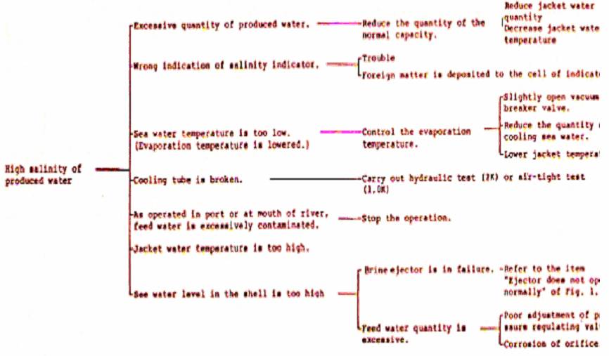
1) Excessive Salt Content in the Fresh Water Produced
Cause i) Disorder of salinity indicator
ii) Too high capacity
iii) Too low evaporation temperature (high vacuum)
iv) The sea water level in the separator shell is too high
v) Condenser cooling tube is leaking
Remedy
i) See "Examination of Deficiencies1 and their Remedy" in Instruction! Manual for Salinity Indicator.
ii) Add a smaller amount of engine cooling water to the heat exchanger by opening the by-pass valve for the engine cooling water.
iii) Open the vacuum breaker valve a little, or add a smaller amount of sea cooling water to the condenser by opening the by-pass valve for sea cooling water.
iv) Check the ejector system (see under too low capacity in the ejector system).
v) The tube should be re-expanded, replaced, or plugged. See also under pressure test of heat exchanger and condenser.
2) Too Low Capacity:
Cause
i) Insufficient heat supply to the heat exchanger
ii) Air in the jacket cooling water side of the heat exchanger
iii) The evaporating temperature is too high
iv) An insufficient amount of salt feed water is admitted to the heat exchanger
Remedy
i) Supply more jacket cooling water to the heat exchanger by throttling the by-pass valve for engine cooling water.
ii) De-aerate the heat exchanger by means of the de-aerating cock.
iii) See under too small feed water supply.
Cause
v) Too large supply of salt feed water is admitted to the heat exchanger
Remedy
v) See under too large supply of feed water
Cause
vi) Scale formation in the tubes of the heat exchanger
Remedy
vi) Inside of the tubes should be pickled.
Cause
vii) No evaporation due to insufficient vacuum
Remedy
vii) Check the air ejector
Cause
viii) The solenoid valve cannot close completely
Remedy
viii) Check the valve for impurities and faults
Cause
ix) The tubes of the heat exchanger on the jacket cooling water side (externally) are fouled
Remedy
ix) Boil out the tubes outside
Cause
x) The fresh water meter gives an incorrect reading
Remedy
x) Check the water meter and adjust it, if necessary
Cause
xi) The produced vapor is not condensed be cause of small amount of sea cooling water for condenser or too high temperature of the sea cooling water
Remedy
xi) Supply more and colder seacooling water to the condenser. (Decrease cooling water quantity for other heat exchanger.)
3) Too High Evaporation Temperature
Cause
i) The thermometer in the separator gives an incorrect reading
ii) The vacuum breaker valve is open
iii) Too high capacity (above 100%)
iv) Too little or too hot
sea cooling water is supplied to the condenser
v) The condenser tubes fouled
vi) Air in the cooling water side of the condenser
vii) The distillate pump does
not remove sufficient water, and the condenser becomes full of water
viii) The capacity of the air ejector is too small
ix) Leaks in the plant
Remedy
i) Exmine the thermometer and replace it, if necessary
ii) Close the valve
iii) By opening the by-pass valve for engine cooling water a smaller amount of jacket cooling water is supplied to the heat exchanger
iv) More or colder cooling sea water is supplied to the condenser.
v) Clean the condenser tubes.
vi) De-aerate the cover of the condenser by means of the de-aerating valve
vii) Examine the distillate pump
viii) See under "Too low capacity of the ejector system."
ix) See under "Testing the plant for leaks."
4) Too Low Capacity of the Ejector System
Cause
i) The pressure of the ejector is too low (smaller than 4.0 kg/cm )
ii) Too high back pressure on the ejectors (higher then 10 m WG measured on the discharge
iii) The ejector pump yields no pressure at all
iv) Too warm water to the ejector
v) The non-return valve in the suction pipe of one of the ejectors is defective
vi) The nozzle of an ejector is worn out
vii) The nozzle in an ejector is during operation clogged up by a welding pearl, a bolt or another foreign body. During standstill the foreign body cannot be detected as it falls back into the ejector water feed pipe
Remedy
i) Check the ejector pump and overhaul the pump, if required. Most suitable ejector inlet pressure is about 4.5 kg/cm .
ii) Open the over-board valve fully
iii) Check the direction of rotation of the pump. De-aerate the pump
iv) If possible colder water is fed to the ejectors.
v) Overhaul the non-return valve.
Take care that the movement of the flap is free and easy
vi) Replace the nozzle
vii) Disassemble and blow out the feed pipe for ejector water
5) Insufficient Supply of Feed Water Cause
i) The feed water pressure is too low
ii) No feed water pressure but water pressure at strainer in feed water line
iii) Feed water orifice defective or clogged up
Remedy
i) Clean strainer in feed water pipe line
ii) Examine the pressure regulating valve in feed water line and raise the outlet pressure by turning the regulating nut, if required. Remember to mount the valve for the flow direction according to the arrow
iii) Take out orifice casing of feed water line and overhaul.
6) Too Ample Supply of Feed Water Cause
i) Feed water pressure too high (higher than 2 kg/cm )
ii) Feed water orifice defective Remedy viii) Replace the diffuser
ix) Diassemble the flange joints and ascertain that there is a free passage through the pipes
Remedy
i) Decrease the outlet pressure by turning the regulating nut of pressure regulating valve or throttle the feed water valve before the feed water orifice
ii) Take out orifice casing of feed water line and overhaul
7) Scale Formation in the Heat Exchanger Tubes
Cause
i) The evaporation temperature is too high
ii) The capacity of the plant is too large
iii) Insufficient supply of feed water to the heat exchanger
Remedy
i) See under "Too high evaporation temperature"
ii) The capacity is reduced by opening the by-pass valve for engine cooling water
iii) See under "Insufficient feed water supply"
8) The Distillate Pump Does not "Take" the Water or does not Extract Sufficient Water
Cause
i) The pump is not giving its full output
ii) The fresh water discharge valve is not open
iii) The leakage of the gland part.
iv) Impurities on the suction side of the pump
v) Too large back-pressure on the pump
vi) The pump is working without back-pressure
vii) The pump has no water
Remedy
i) Check the direction and the number of revolutions of the pump. If required, overhaul the pump and replace the casing rings
ii) Check the valve
iii) Tighten the gland part
iv) Remove the impurities
v) Reduce the back-pressure Max. 2.0 kg/cm2
vi) Throttle the outlet valve of the pump
vii) Stop the pump and break the vacuum so that the water flows to the pump
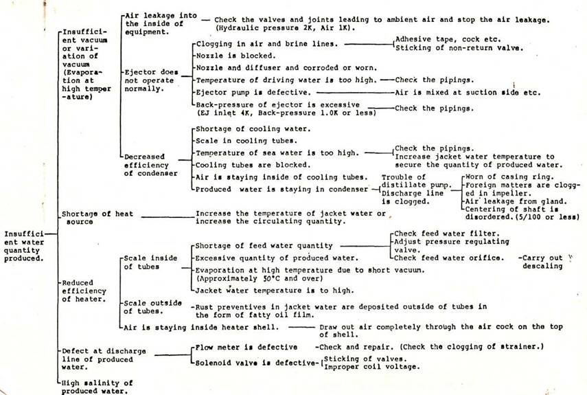
If the Fresh Water Generator does not work satisfactorily, and if the engine room staff cannot adjust it to do so by means of the instruction manual, we recommend that the accompanying control forms should be filled in the sent to Sasakura, who on the basis of the control forms usually can give the reasons for the unsatisfactory result.
DEFICIENCIES AND CAUSE OF FRESH WATER GENERATOR

INSTALLATION OF THE FRESH WATER GENERATOR
The Fresh Waters-Generator should be connected to the normal cooling water installations of the diesel engine as will be seen from the pipe diagram inserted. The generators are fastened on bed for instance, bulk head or ship sides by the brackets on the back of the generator top. (Welding or soldering on the generator must not take place as the inside Neoprene Coating is thereby damaged.)
The bottom blow-off valve of the heat exchanger must have a free outlet so as to enable regular removal of sea water from the generator during standstill. Space must also be reserved for drawing out condenser tubes, disassembling and examining the ejectors and taking out the heat exchanger body. After dismounting the distillate pump, the shell of the heat exchanger is drawn out towards the front side of the generator by turning a little.
The heat exchanger is connected to the engine cooling water system in series with the fresh water cooler. Instead of the indicated connection in series with the fresh water cooler the heat exchanger can be connected in parallel with the fresh water cooler. The latter way of connection reduces the pressure loss in the engine cooling water system, but the regulation of the engine cooling water will be more difficult. (The heat exchanger inlet of the jacket cooling water should be connected to the upper connecting part.)
The pressure drop through the heat exchanger is normally 0.2 - 0.25 kg/cm2 , but at especially low jacket cooling water temperature - and the corresponding larger amounts of water - it may reach 0.5 kg/cm2 . The sea water fed to the condenser must be as cold as possible. This is especially important when the ship sails on the very warm sea water area. It is desirable that the sea water pipe to condenser is connected to the flange on the side of the nozzle of the de-aerating pipe from the condenser to the water ejector.
The condenser should preferably by connected ahead of the other coolers of the diesel engine. It can also be connected before the fresh water cooler or in parallel with same which naturally causes warmer sea cooling water being fed to the condenser of the Fresh Water Generator and consequently a possible reduction of the capacity of the generator.
The pressure drop in the condenser is 0.35 - 0.5 kg/cm2, but at especially high cooling sea water temperatures - and the corresponding larger amounts of cooling sea water - it may reach 0.6 kg/cm2 .
The dimensions of the pipes for jacket cooling water and cooling sea water must in each case be determined in consideration of the permissible pressure loss and the permissible water velocity in the pipes. As a rule., pipes of the same dimension as the branch on the Fresh Water Generator will be fully satisfactory.
The ejector system for suction of sea water and gasses must in order to obtain the desired capacity be supplied with sea water at a pressure of min. 4.0 kg/cm2 . The ejectors must not operate at a pressure head of more than 10 m WG (14.2 p.s.i.g.) (Measured on the discharge branch for the ejector system).
The outlet pipe for the ejector water and condenser cooling water respectively can normally be made with the same dimension as that of the corresponding branch of the Fresh Water Generator. Cooling sea water must always be returned to the cooling sea water line after passing through the condenser. It is only when the condenser is connected in parallel with the fresh water cooler or when the sea cooling water pump has enough capacity that the sea cooling water may be discharged overboard. The ejector pump should be installed at the place of below Unloaded Water Line, separately from the fresh water generator. As the capacity of the ejector falls with increasing sea water temperature the ejector pump should preferably draw cold sea water direct from its own sea valve, and it should be avoided that overboard valves for dirty water, oil, etc, are placed close to this sea valve.
The rnanometeric delivery head of the pump is about 48 m WG and the dimensions of the pipe line between ejector pump and branch for ejector system of the Fresh Water Generator must be chosen for an ejector water pressure of min. 4.0 kg/cm2 at the generator. Normally a pipe line of the same dimension as the Fresh Water Generator branch for ejector water supply will be sufficient.
The distillate pump is mounted on the Fresh Water Generator.
On the discharge pipe of the pump, a non-return valve, a cell for salinity indicator, and a water meter are fitted.
Pump outlet pressure is about 2 kg/cm2 and the fresh water pipe from the generator to the fresh water tank must be dimensioned accordingly considering the geometric difference in heights and the pipe resistances.
Motors and starters should be connected as shown in the wiring diagram to be found in the starters and motor terminal boxes. Check that the direction of rotation of the pumps is correct.
NOTE: The pumps must not run without water in order not to damage the pump gland seals.
Salinity indicator is mounted on the instrument board of generator and connected as indicated in the special instruction manual for the salinity indicator.
The solenoid valve which is delivered with the salinity indicator is mounted before the non-return valve for impure water line and the discharge from the non-return valve should be connected to the separator shell of the Fresh Water Generator.
Vacuum test of the Fresh Water Generator
Starting of the Fresh Water Generator is facilitated by first examining whether the generator is completely air-tight. This is done by closing the outlet valve of the distillate pump, vacuum breaker valve, bottom blow-off valve and feed water valve and opening the overboard valve and sea valve for the ejector system. Thereafter the ejector pump is started and when the vacuum gauge shows about 70 - 70.5 cmHg V.
If the Fresh Water Generator is completely tight the vacuum gauge pointer should now remain in its position, but as there will always be some tiny leaks, for instance, at the stuffing box of the distillate pump shaft, especially when the pump is not working, and at valve spindles etc., some air will gradually leak into the Fresh Water Generator, and the pointer of the vacuum gauge will fall. However, it will usually be possible to ascertain, whether there are any significant leaks as it will then be difficult to create a vacuum in the Fresh Water Generator, and when the ejector pump is stopped the pointer of the vacuum gauge will fall within a short time. If the vacuum has fallen more than 2% in 8 hours the leaks must be considered so large that inspection and sealing are required. Possible leaks can most easily be found by a pressure test with 1.0 kg/cm water pressure.
During the above vacuum test the heat exchanger will normally be filled with sea water through the feed water line. As will be seen below it is advisable not to make the test in polluted water.
Starting of the Fresh water Generator must not take place in polluted water, for instance, in a dockyard or in a port as at such places the sea water is usually heavily infected with bacteria that can foul the Fresh Water Generator and make comprehensive cleaning the disinfection of the entire fresh water system on board the vessel necessary.
NOTE:
Welding must not be carried out on the shell(separator shell, upper cover and bottom cover of the heat exchanger) of the Fresh Water Generator, nor should the shell be exposed to high temperatures in other ways, for instance, steam, as the inside Neoprene Coating would thereby be damaged.
7. OPERATION BY STEAM
Distillation can be achieved also by steam instead of jacket cooling water.
For operation with steam, a built-in steam injector is to be used.
1) OPERATION SEQUENCE
The vacuum in the shell should be more than-70 cmHg-V. Feed water should be supplied in normal condition and always at a pressure within the range of green mark on the feed water pressure gauge. Before starting operation as mentioned below, see if sufficient cooling sea water is being supplied to the condenser.
(1) Close the inlet and outlet valves of jacket cooling water completely, and open the valves in the jacket water outlet line (for drainging jacket cooling water). As it is not contain various kinds of unti-corrosive chemicals, drainage of such cooling water should be accelerated by opening the air vent cock.
(2) After blowing jacket cooling water, shut the jacket water outlet and then supply fresh water usable for boiler to the heater (shell side), pipings and the steam injector.
When they are competely filled with water, which can be ascertained by opening the air vent cock, close the fresh water inlet valve (for filling fresh water).
(3) The cock at the top of the drain pipe shall be always opened because it serves as a syphone breaker.
(4) After the above-mentioned preparation, open the steam valve before the steam injector gradually in order to let steam in. Fresh water in the piping is circulated as well as heated by steam. As heating fresh water is cooled in the heater, steam drain goes up through the drain pipe and then it is exhausted into the drain tank.
2) CAUTION
(1) Fill the heater (shell side) and the pipes with fresh water.
If there is air inside the shell, neoprene coating may be damaged by abnormal rise in temperature. Such air will also cause abnormal noise or vibration due the cabitation or pulsating movement of inside water.
(2) Do not open the steam valve rapidly. If so, water in the shell will pour into the drain tank and cause vibration.
(3) If steam pressure is lower than the designed value, inside water wi] pulsate and cause abnormal noise and vibration.
3) REMARKS ON THE INSTALLATION OF THE STEAM INJECTOR
(1) If the back pressure is exerted to the discharge line of the steam drain of the steam injector, extraordnary vibration many occur in the injector and there is a possibility that the operation of the system may become impossible. As the limit of this back pressure varies in accordance with the supplied steam pressure, piping must be carried out referring to the following criteria.
Supplied steam pressure (atg)
3.0 kg/cm2 G
4.0
5.0
6-10
Back pressure (max).
Max. 3 mAq
4
5
6
* In general, as the supplied steam pressure becomes higher, the resistance against the back pressure tends to become larger by that degree.
(2) If the supplied steam pressure is lower than the designed pressure, the same vibration may be caused to the system. The fluctuation from the designed value must be within about + or - 5 %.
(3) The heating drain outlet pipe of the steam drain discharge is necessary only when the drain tank is located lower than the installation position of the distilling plant. The height of this heating drain outlet pipe is min. 1500 mm from the base surface of the plant.
(4) Valves must not be contained in the discharge line of the steam drain. This is because the fact that the valves are located in the drain line and the operation is carried out with the valves closed, the steam pressure is exerted to the shell side of the heater of the distilling plant, for the reason that in general the supplied steam pressure is higher than the design pressure (3.3 kg/cm G) of the heater shell.
PIPE DIAGRAM OF FRESH WATER GENERATOR
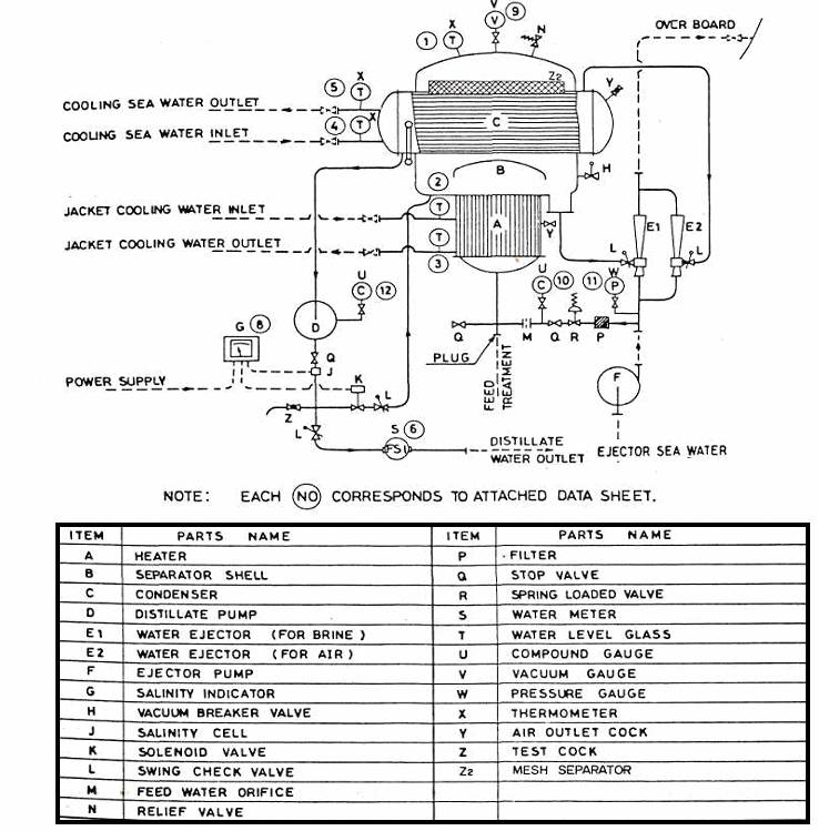
SKELETON OF INTERNAL ARRANGFMFNT FOR FRESH WATER GENERATOR
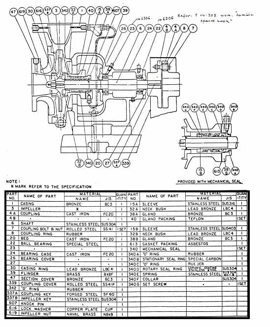
SECTIONAL DRAWING EJECTOR PUMP
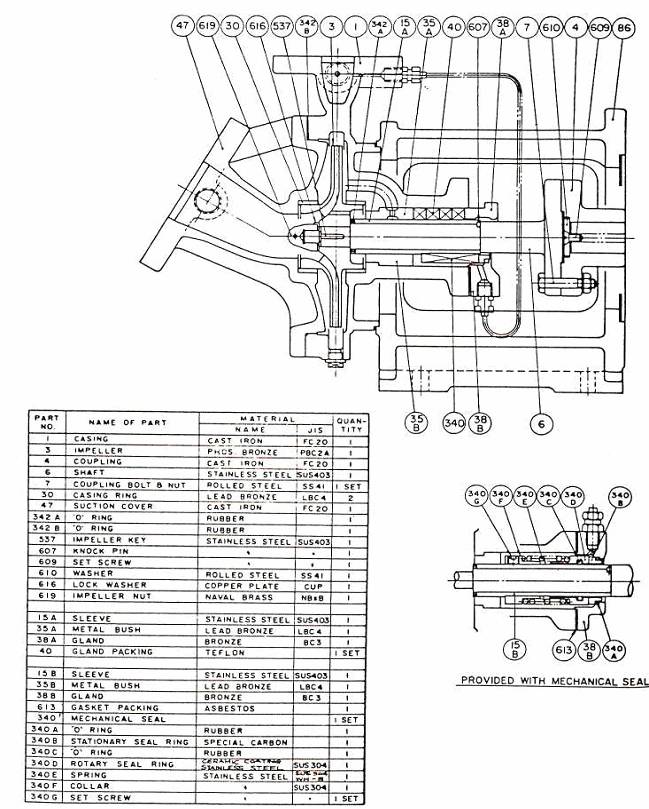
SECTIONAL DRAWING OF DISTILLATE PUMP
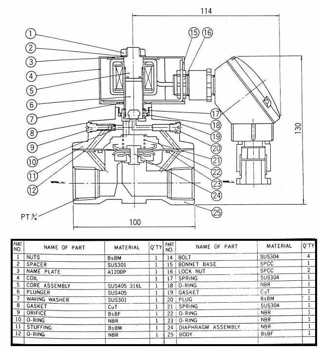
SECTIONAL DRAWING OF WATER EJECTOR
SECTIONAL DRAWING OF WATER METER
