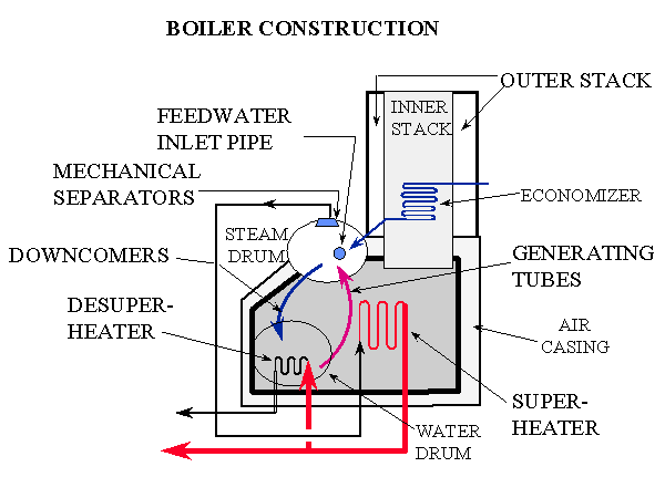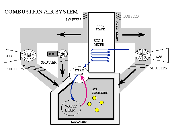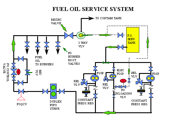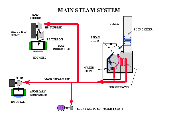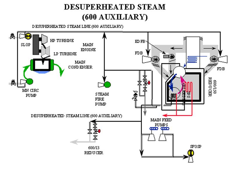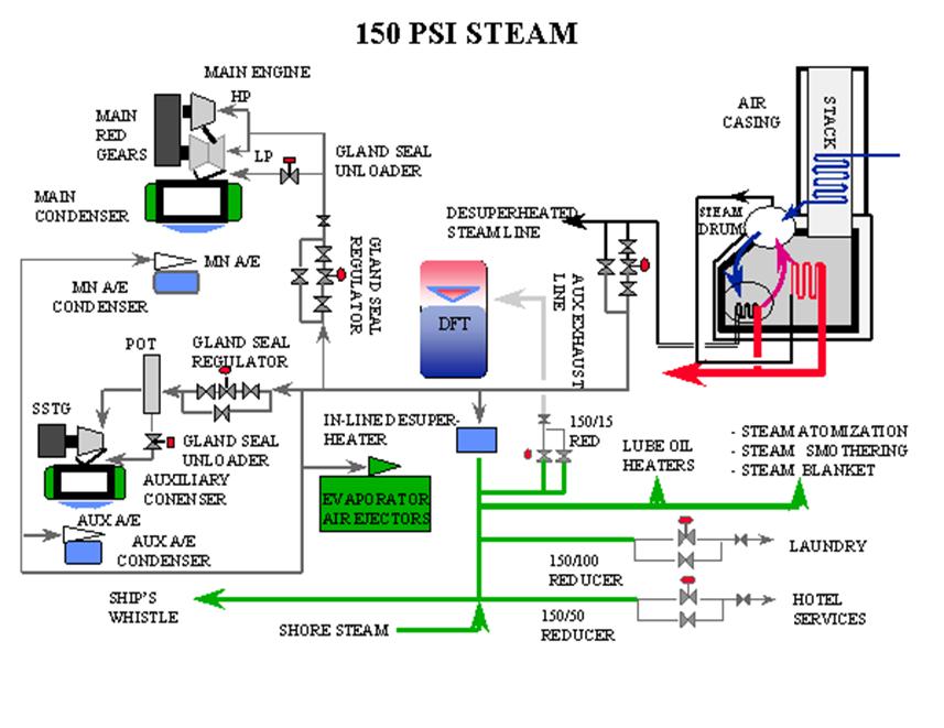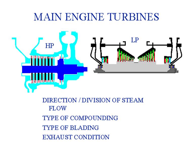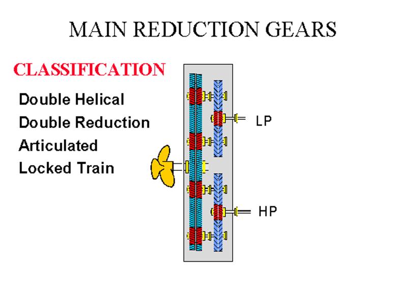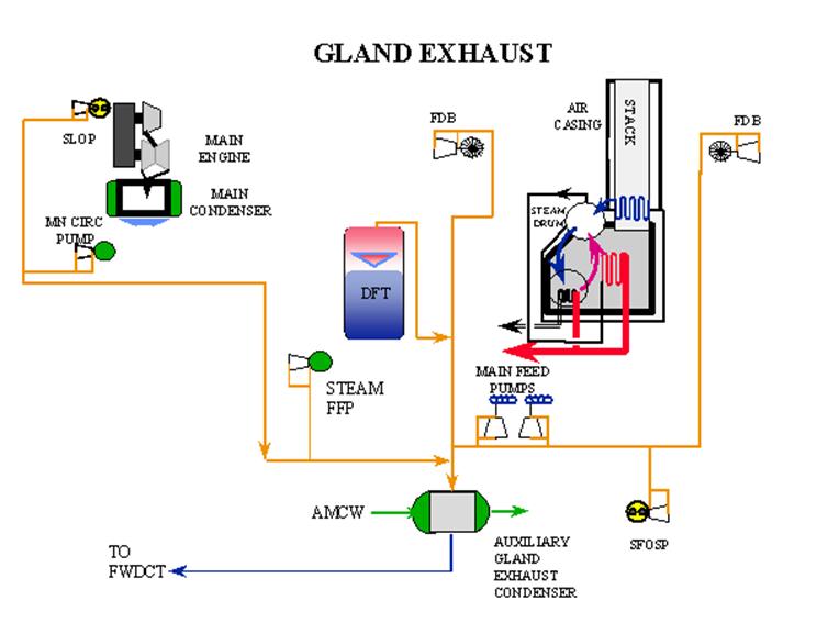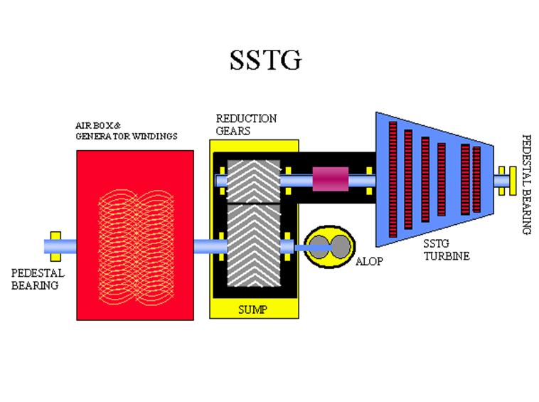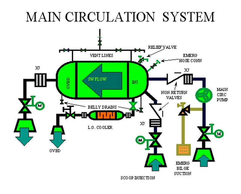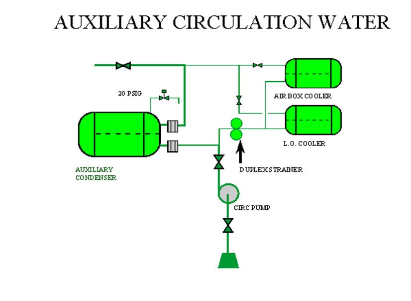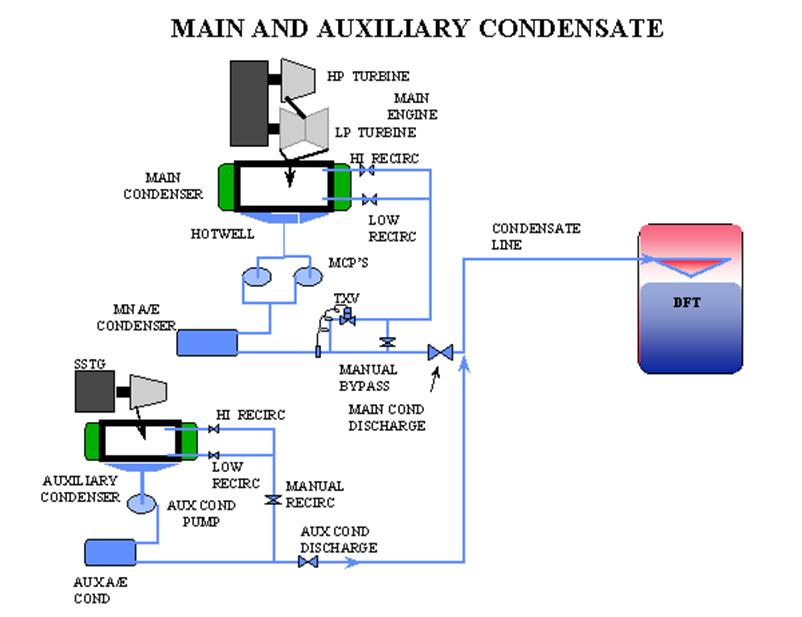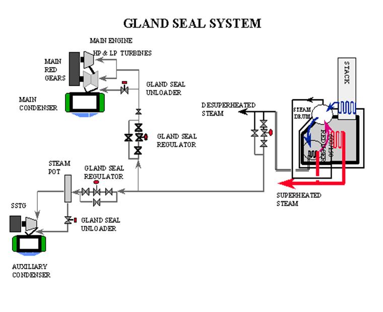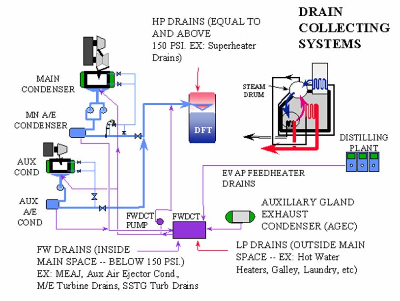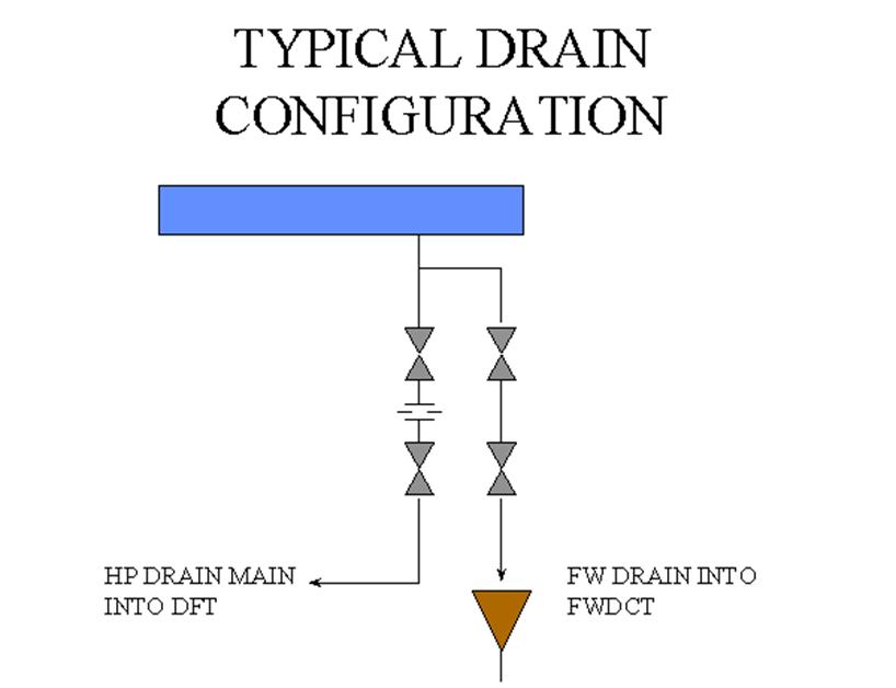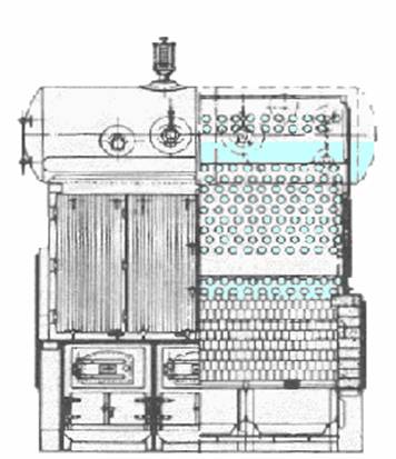

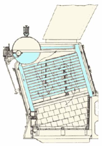
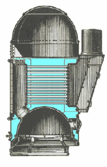
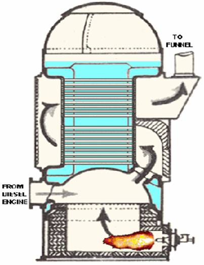
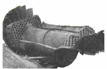
The boiler has a dome-shaped furnace top that forms the bottom of the boiler itself. It has a neck on the front through which the boiler is fired and there is another on the rear part of the top that leads to a higher located combustion chamber. The combustion chambers backside is covered with brickwork and from its front-side a horizontal bank of flue-tubes leads to the smoke box on the front side of the boiler.
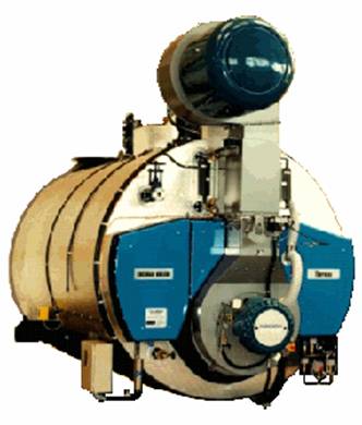
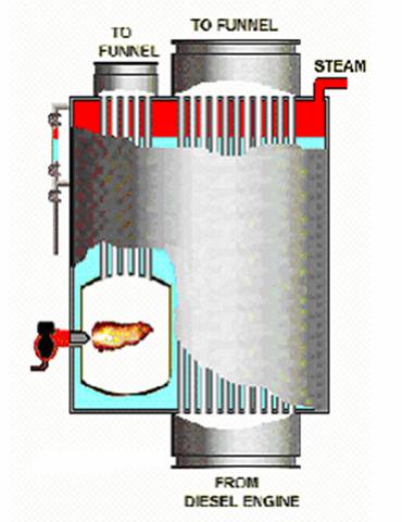
The composite marine steam boiler is a combination of an oil-fired steam boiler and an exhaust gas economizer. When the diesel engine is at full load the fuel oil burner only starts if the steam demand exceeds the steam production achieved from the diesel engines exhaust gases.
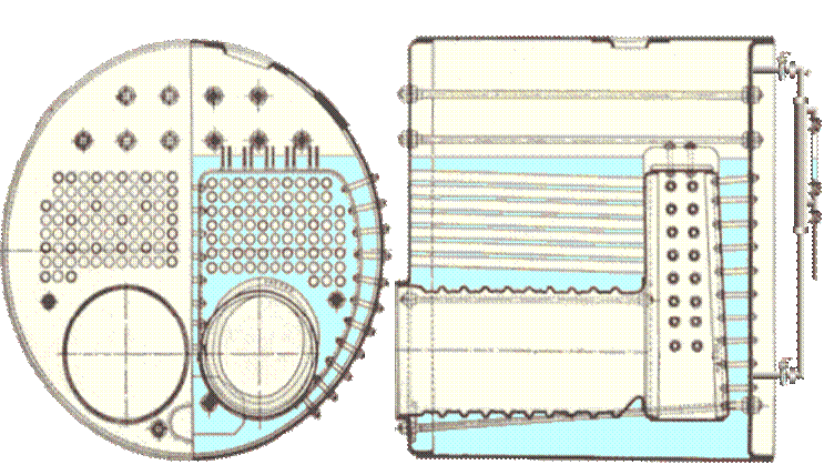
The single-ended return tube Scotch boiler consists of a cylindrical boiler shell of large diameter and short length, provided with two or more furnaces in corrugated fire-tubes. Each furnace ends in a combustion chamber, surrounded by water. The gases pass through a bank of flue-tubes from the combustion chamber to the smoke-box at the boiler front
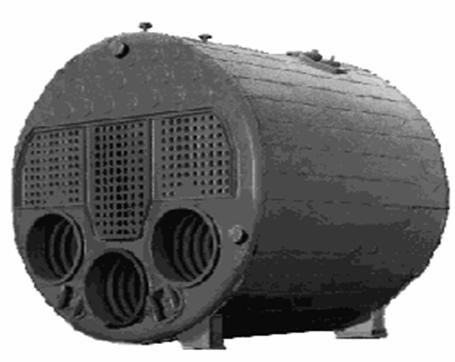
The Scotch fire tube boiler contained a large quantity of water, about six times more than a water-tube boiler, and was therefore slow to steam up and to change the output capacity. Due to the boilers stiff construction it required also a long steaming up period to avoid leaks caused by thermal expansion of the material.
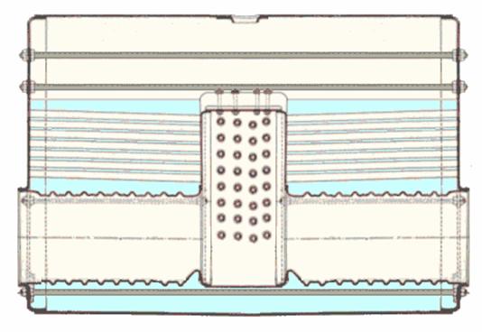
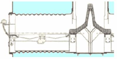
When the furnace door was open, cold air could hit the combustion chambers opposite wall and cause tube leakage. To prevent that a high baffle of firebrick was installed in the middle of the combustion chamber.
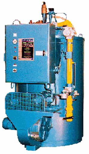
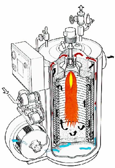
The
Vaporax steam generator
Because
of the innovative design, the rise to working pressure can take place
in 3 minutes starting from a cold boiler in stand-by. This
characteristic as well as the low volume of water reduces the thermal
losses and therefore helps to keep the operating costs low.
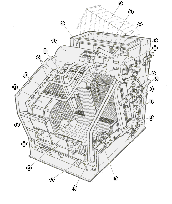
B.
Economizer
A heat exchanger that transfers heat from Boiler Flue
Gases to Boiler Feedwater.
C.
SteamOutlet
Saturated steam from the SteamDrum to the Superheater
D.
Cyclone
A device inside the drum that is used to prevent water and
solids from passing over with the steamoutlet.
H.
Superheater
A bank of tubes, in the exhaust gas duct after the
boiler, used to heat the steam above the saturation temperature.
I.
Superheater Headers
Distribution and collecting boxes for the
superheater tubes.
L.
Waterwall Header
Distribution box for waterwall and downcomers.
N.
Waterwall
Tubes
welded together to form a wall. ![]()
O.
Waterwall Header
Distribution box for waterwall and downcomers.
R.
Waterwall Header
Collecting box for waterwall and risers.
S.
Riser
Tubes in which steam is generated due to high convection or
radiant heat. The water-steam emulsion rises in these tubes toward
the steamdrum.
T.
Downcomer
A tube through which water flows downward. These tubes
are normally not heated, and the boiler water flows through them to
supply the generating tubes.
U.
SteamDrum
Separates the steam from the water.
V.
Economizer Header
Distribution box for the economizer tubes.
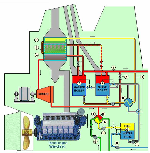
A.
Economizer section
Preheats the circulating water before it enters
the evaporator tubes.
B.
Evaporator section
Water evaporates and emulsion of steam and
water flows back to the boiler.
C.
Superheater section
Superheats the steam for the turbine.
D.
Heat exchanger
Preheats the boiler feedwater.
E.
Condenser
The exhaust steam from the turbine and excess steam from
the steam system condense and recycle.
F. Condensate pump
G.
Cooling water pump
Seawater.
H.
Make-up water pump
From softener unit.
I. Boiler feedwater pump
1.
Steam pressure control
The pressure control loop adjusts the
burner load according the steam demand.
2.
Water level control
A simple control loop will do for a boiler
with large amount of water and relatively small steam output. To
minimize shrink and swell at start and stop of the burner it would be
wise to have two setpoints for the water level. A lower level (abt.
40%) when the burner is stop and a higher (abt. 50%) when it's
firing.
3.
Economizer inlet temperature control
The feedwater is pre-heated
in order to increase the efficiency of the plant. The circulating
water to the exhaust gas boiler heats the feed water and the
three-way valve on the inlet to the heat-exchanger controls the
temperature. The economizer inlet temperature must never fall below
135°C to avoid corrosion on the economizer tubes.
4.
Condenser pressure control
An absolute pressure transmitter and a
controller adjust the cooling-water to the condenser to protect the
condensate from being cooled down more than necessary.
5.
Condenser level control
The level controller actuates the
condensate outlet control valve.
6.
Feedwater tank level control
The level controller actuates the
make up water control valve.
7.
Steam dump control valve
Takes care of excess steam from the
waste heat boiler when the steam production exceeds the steam demand.
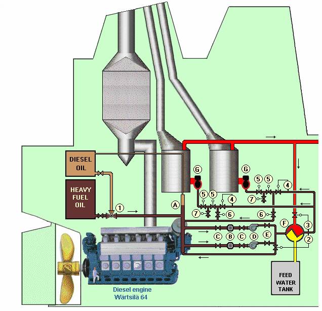
A.
Fuel Oil header
The Fuel Oil header should be a standing up
relatively large pipe with a deaeration pipe to a higher level than
the fuel oil service tanks; some times it's connected to the top of
the diesel oil service tank.
B.
Fuel Oil filters
Clean the Fuel Oil filter frequently. If the
filters are clogged the fuel oil might vaporize in the pump and cause
damage. A differential pressure meter across the filter would be a
good help to have the filters cleaned in time.
C.
Shut off valves
Shut off valves for cleaning of the filters. The
valves should normally be open.
D.
Fuel Oil pumps
Each pump should have sufficient capacity to run
both boilers on maximum load. Normally one pump is running and the
other is standing-by. The stand-by pump should start upon low
pressure in the process line rather than being started upon a pump
motor failure.
E.
Shut off non return valves
These valves have to be non-return
type, or a shut off valve and a non-return valve. The valves should
always be open on both pumps, so the stand-by pump can start
automatically.
F.
Fuel Oil heater
The fuel oil heater is a heat exchanger that must
have a safety relief valve.
Always install a safety relief valve
if a fuel oil volume can be shut up and heated.
G. Burners
1.
Change over valve, Heavy Fuel Oil to Diesel Oil
The three-way
valve ought to be provided with a limit switch that breaks the
electric circuit and shut off the fuel oil heating valve, in the
control loop 3 , avoiding the diesel oil from being heated over its
flashpoint.
2.
Fuel oil pressure control
The pressure control loop adjusts the
fuel oil pressure by means of the pressure controller and the fuel
oil return valve. The pressure is measured after the fuel oil heater
to get accurate pressure to the burners. The return valve before the
fuel oil heater recycles cold fuel to protect the pumps from
overheating.
3.
Fuel oil temperature control
The temperature control loop adjusts
the fuel oil temperature by means of the temperature controller and
the steam inlet control valve. The temperature controller's set point
should be set to assure an adequate fuel oil viscosity for the actual
burners.
Sometimes the control valve is installed in the
condensate outlet line. This requires a smaller control valve and the
control function works even better. However, this installation is for
some reason not so very common.
4.
Fuel oil flow control
On large boilers the fuel oil flow
controller gets its setpoint from the burner management system or the
airflow controller to achieve a proper air-fuel mixture.
On
smaller boilers the fuel oil flow control valve often is connected to
the combustion air damper by means of a metal rod or wire.
In
both cases the steam pressure in the boiler sets a suitable fuel oil
flow.
5.
Fuel oil shut of valves
Almost every classification society and
other authorities requires two shut of valves for the fuel oil,
mechanically in series and electrically in parallel.
6.
Fuel oil recirculation valve
This valve does not always exist,
but if it does, the valve should open when the fuel oil shut of
valves closes. The recirculation has advantages and disadvantages.
· The advantage is that it keeps the fuel oil line warm when the burner is off.
· The disadvantages is that it will, in the long run, heat up the fuel oil passing through the oil pump that might cause problem with cavitations.
Leading the recirculation fuel oil back to the fuel oil service tank wouldn't be wise. The fuel oil's temperature often exceeds 120ºC and water that might occur at the bottom of the tank will vaporize and in worst-case cause damage to the tank.
7.
Fuel oil drain valve
Some authorities require a drain valve to be
installed between the shut off valves. The burner management program
mustn't open the drain valve before the shut off valves are totally
closed and it should close the drain valve before the shut off valves
open.
The
marine steam boilers on board in ships nowadays have become a less
evident part of the engine room than they were in the old days.
However, the marine steam boilers are still important parts of the
system, especially if the main engines are running on heavy fuel oil
that need to be heated. I don’t want to go through the entire
instruction book for the marine boiler but just point out one
important matter.
As we all know, a very thin layer of oil on the
surface of the boiler tubes or any of the direct heated surfaces of a
boiler might cause local overheating of the material and possible
damage to the boiler. What we maybe not know is how very small
quantity of oil it requires to get a dangerous situation. A tube
break in a fuel oil heat exchanger is very easy to detect, a simple
detector in the hotwell will manage that, but a small crack in a tube
may cause you an even more serious problem.
A tiny oil leakage
giving some 15 to 25 ppm of oil in the boiler feedwater would not be
visible; the water is still limpid. Yet this apparently insignificant
oil pollution might causes sever danger to the boiler. If a boiler
has a capacity of 20 tons of steam per hour at full load and the feed
water is polluted with 25 ppm of oil, then it will accumulate
approximately 12 kg oil in the steam drum per day. A bucket of oil in
the boiler every day; I suggest that you buy yourself a sensitive oil
detector.
It will cost you, but it might save you from some
future cost of repairs.
N.B. ppm=parts per million.
1
ppm=1kg per 1000 metric tons or
1 ppm=2 lb. per 1000 short tons.
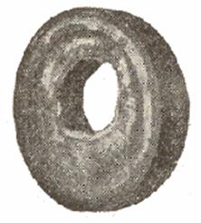
An oily ring inside the water gauge glasses at the water level is a serious warning.
The mineral and organic substances present in natural water supplies vary greatly in their relative proportions, but are principally comprised under the carbonates, sulphates and chlorides of lime, magnesia and sodium, iron and aluminum salts, silicates, mineral and organic acids, and the gases oxygen and carbon dioxide.
Scale is formed from the carbonates and sulphates of lime and magnesia, and from the oxides of iron, aluminum and silicon and it will result in:
Reduction in the boiler efficiency because of the decreased rate of heat transfer.
Overheating and burning of tubes resulting in tube failure.
Scales
are dangerous long before it reaches this thickness.
A very thin
scale can cause tube failure due to overheating.
Scale has about
one-fortyeighth of the heat conductivity of steel.
A scale
thickness of about 1 mm (0.04") can be sufficient to reduce the
heat transportation to a dangerous point; when the water inside the
tube cannot receive and carry away the heat fast enough from the tube
metal to keep its temperature below its fusion temperature, resulting
in the tubes "burning-out".
Using an open or direct contact feed water heater, where the water is raised to near-steam temperature is the most effective, the cheapest and the most convenient system of de-aeration.
Heating boiler feedwater by means of exhaust steam effects a saving of about 1% of fuel for each 6ºC rise in the temperature of the feedwater. Consequently, heating the water from 10° to 99ºC saves about 14% fuel.
Besides the fuel saving, heating the feedwater increases the actual steaming capacity of the boilers. Using surplus of exhaust steam, above that required for heating the boiler feedwater, to heat buildings will realize additional economies. If all of the exhaust steam from engines or turbines can be utilized for heating during the heating season, it will pay to shut down the condenser.
The first and most important use for the exhaust steam is to heat the feedwater, since all of the heat of the exhaust steam so utilized returns undiminished to the boilers.
Lesser temperature difference at the feedwater inlet to the steam boiler reduces thermal stress in the material.
Higher feedwater temperature reduces the shrinks and swell in the steam drum and simplifies the water level control.
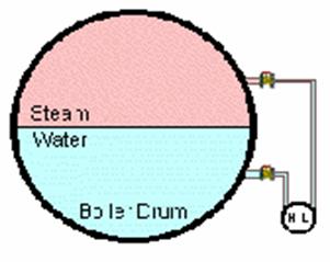
Differential
pressure measuring transmitter.
This method uses normally a
differential pressure measuring system with "wet leg", that
is, the impulse pipes to the positive measuring point below the
lowest water level and the impulse pipe to the negative measuring
point above the highest water level, are both filled with water. The
differential pressure signal is normally elevated so the output
signal corresponds to the level in the boiler. 0% of water in the
level glass correspond to 4 mA (3 psi) and 100% corresponds to 20 mA
(15 psi). The measuring result is insensitive to foam in the boiler
drum since the measuring method is based on the weight of the water.
Capacitance measuring electrode transmitter.
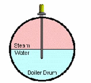
An
insulated electrode is placed in the boiler and the length should be
sufficient to reach the water at all acceptable levels. The insulated
electrode and the boiler work as a capacitor with the water and the
steam as a variable dielectric medium. The capacitance of the
”capacitor” is converted into a current signal. 0% of
water in the level glass corresponds to 4 mA and 100% corresponds to
20 mA. The measuring result is rather sensitive to foam in the boiler
and deposits on the electrode influences negatively on the measuring
results.
This method is relatively new as level control in steam
boilers although it has been used for a long time for dry substances
such as grains in warehouses.
Conductivity measuring electrode level switch.
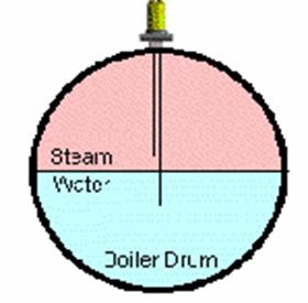
An
electrode is placed in the steam dome and the length of the electrode
decides the level where the alarm shall occur. A low voltage
alternating current passes through the water in the boiler to the
electrode and the circuit breaks when the water level falls below the
end of electrode. This method is mainly used for high and low level
alarms. It is also used, in small size boilers, to start and stop the
feed water pumps. Deposit on the electrode is not a problem. Normal
degree of coverage does not disturb the measuring results. The
measuring result is sensitive to dense foam in the boiler.
It’s
normally one electrode for emergency low water level alarm, or two
electrodes if also high level alarm is required. This water level
sensing method is also common on small boilers for start and stop of
the feed water pumps. Up to six electrodes can be used in one
electrode stand
Level float switch.
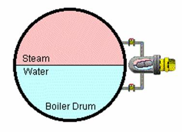
Level
float switches have been used for decades as level switches in
boilers, but nowadays electrodes have replaced them. Moving parts are
hard to check in boilers and deposit on the hinge may seriously
disturb the function. The measuring result is rather insensitive to
foam in the boiler.
Level displacer transmitter.
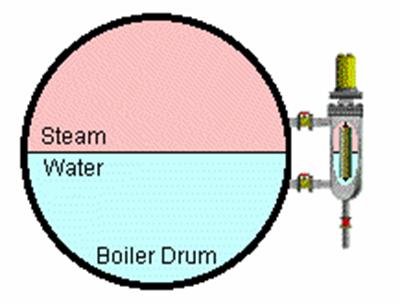
A
level displacer (a float heavier than the water) is suspended to a
spring balance by means of a stainless steel cable or a rod. When
semi-submerged the weight of the displacer changes when the water
level varies and the change in weight is converted into a level
signal that corresponds to the level in the boiler. 0% of water in
the level glass correspond to 4 mA (3 psi) and 100% corresponds to 20
mA (15 psi). This level measuring method is not so very common
onboard ships since the measuring result is very influenced by the
ship’s movement. Ashore, on the other hand, it works very well.
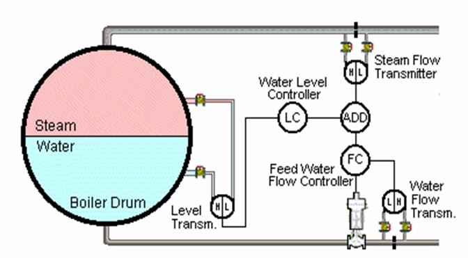
In
a boiler drum exist water and steam at saturation pressure and
saturation temperature. Furthermore, the water is mixed with steam
bubbles in different sizes. If one opens the valve to a steam
consumer then the pressure in the boiler drum falls and hence the
steam bubbles expand and the water level rises despite the fact that
the water mass actually decreases. On the other hand, pumping in cold
feed water will cause the steam bubbles to collapse and the water
level falls when the water quantity actually increases in the steam
drum. These shrinks and swell phenomena will complicate the control
of the boilers steam drum level.
For a boiler with large amount
of water and relatively low steam production a single water level
transmitter on the steam drum is sufficient for the level controller
to maintain a level with acceptable variation.
Far more
sophisticated methods are required for boilers with high steam
production and relatively small water volume. The classic method
works as follow: The outlet steam-mass is measured and the inlet
feed-water-mass is adjusted to the very same amount. The level
transmitter is merely used to tune up the system so the water level
lies within the limits.
Thus, the setpoint to the feed water flow
controller is the sum of the outlet steam flow signal and the
reversed water level controllers signal minus 12 mA (or 9 psi if it
is a pneumatic system).
Add to the monthly maintenance list:
Check the process impulse piping between the steam outlet line and the steam flow transmitter. Fur deposit is very common in the orifice’s measuring holes.
Check
the process piping between the steam drum and the water level
transmitter. Condensate has to accumulate in the tubing before the
transmitter can work properly again.
Draining the level
transmitter that often wouldn’t be necessary if you have
stainless steel tubing between the boiler drum and the level
transmitter.
N.B. the feedwater flow controller has to be in manual mode during these procedures.
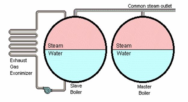
Keeping
a slave boiler pressurized.
In a two-boiler system it’s
often a problem to keep the slave boiler at operation pressure when
the steam demand is low. This problem does not appear when the vessel
is loading or unloading in a harbor since those operations normally
need both boilers. On the other hand, when the ship is at sea and
only one oil-fired boiler is used then the slave boiler tends to cool
down far below the required stand by conditions.
Different methods
have been used to solve this problem. Installing steam heating coils
in the bottom of the boiler is one method and a sophisticated
start-and-stop method for the slave boiler’s burner to keep the
pressure at desired level is an other.
These installations will be
unnecessary if you happened to have an exhaust gas economizer.
Just
connect the exhaust gas economizer to the slave boiler instead of the
master boiler. This operation method will guaranty normal operation
pressure on both boilers all the time at sea. The method has been
used in many ships and the chief engineers are satisfied with the
result.
A
colorless fuming liquid, N2H4, derived from diazoacetic acid: used as
a reducing agent in organic synthesis and as a fuel in jet
engines.
Used in boiler feed water treatment, to reduce oxygen in
the system, the normal level of hydrazine reserve to be maintained in
the water is between 0.1 and 0.3 ppm. The chemical reaction with
oxygen can be expressed as: N2H4 + O2 ==> 2H2O + N2
Excess
hydrazine, in a boiler, breaks down to produce ammonia that has
beneficial effects in raising the pH of the steam/condensate system
and thus affords some protection to the system by neutralizing any
carbon dioxide.
The reaction can occur in two ways:
3N2H4 ==> 4NH3
+ N2
2N2H4 ==> 2NH3 + N2 + H2
Hydrazine should be handled with care since it is allergenic and carcinogenic to humans.
Marine boiler plants require adequate control systems to raise steam, maintain design conditions for steady steaming, secure the boiler units and detect promptly malfunctions and failures. The automatic control arrangement on a shipboard boiler is divided into two parts:
Safety system that controls that all values are within the predetermined limits and give automatic alarm if some of them are not, and also initiate an automatic burner trip in case of a dangerous situation.
Continuously control of the different parameters for water level control, steam pressure control, fuel oil pressure control, fuel oil temperature control, blowdown control, superheat temperature control etc.
The combustion control system maintains constant steam pressure by controlling the flow of air and oil to the burner. The more advanced combustion controls transmit the air and oil loading simultaneously but with a slight lag between air and oil, so that with an increased boiler load, the air will lead the oil, and on a decrease in the boiler load the oil will lead the air. Such an arrangement makes it possible to minimize the emission of smoke during maneuvering. All the classification societies have special requirement for marine applications due to the environment and the fact that one can't escape from an accident nor get service when the ship is sailing at sea. Things just have to work.
An
easy way to find out if your boiler control system lights up the
first burner safely.
Safely
shut off the fuel supply to the burner before the test.
1. Power up the boiler control system.
2. Start the burner.
3. Start a stopwatch when the combustion air damper has reached its maximum position.
4.
Stop the stopwatch when the combustion air damper begins to close
again, and note the purge time. The air in the furnace should be
changed at least five times during the prepurge period.
Find the
furnace volume and the fan capacity from the documentation’s
and calculate the purge time needed. The time must never be less than
fifteen seconds even if your calculation says so.
5. Start the stopwatch again when the automatic fuel oil shutoff valves open.
6.
Stop the stopwatch when the fuel oil shutoff valves close and you get
a flame failure or misfiring alarm, and note the trail-for-ignition
time. If the time you get is more than fifteen seconds, then you must
not ignite the burner ever, until the time has been adjusted. Five
seconds is a relevant trail-for-ignition time, but different
classification societies specify different maximum time. Get the
correct maximum time from the rules of the actual classification
society.
N.B. This shut off delay is only allowed during
trail-for-ignition. When you got at flame failure during normal
firing the fuel oil valves must shut off instantly.
Some further checks to improve the safety
1. The fuel oil flow during light-up must not exceed 20% of the full load flow, but in burners with limited turndown ratio the burners minimum load has to be accepted.
2. A corrupt flow transmitter signal may cause sever problems therefore:
· When purging the furnace whit air prior to light-up the position of the combustion air damper should be confirmed by means of a limit switch rather than relying only on the air flow transmitter's signal.
· At burner light-up the position of the fuel oil control valve and the combustion air damper should be confirmed by means of limit switches rather than relying only on the flow transmitters' signals. You should of course use the transmitters' signals, but they ought to be confirmed to be reasonable by means of limit switches.
3. Direct the light from a flashlight onto the flame scanner sensors, when the burner is off, to confirm that the auto-check-function works correctly and you get an alarm. If you get any other action, such as opening of the fuel valves, then your system needs a thorough improvement.
4. Using the igniter during the post-purge of the last burner's lance (or a single burner's lance) has some disadvantages. Upon reset of the system, after a flame failure, the igniter will start firing before the furnace has been properly purged with air, which will cause impending risk of furnace explosions. Consider the following:
· A well-tried method is to purge the fuel line and the burner-lance slowly to let the fuel continue to burn, without igniter support, until the lance is empty.
· Not purging the burner-lance at all is an other method, but it requires a stand-by heating of the tubing and the lance to keep the fuel sufficiently heated to be floating.
· What ever you do, secure that the igniter not under any circumstances starts before the furnace has been properly purged with air.
Back to the question in the headline, is an automatic controlled boiler an explosion risk?
|
In automatic mode and properly adjusted: |
No |
|
In manual mode, skillfully operated: |
No |
|
In automatic mode and not properly adjusted: |
Yes |
|
In manual mode, not skillfully operated: |
Yes |
How
to make a control loop fail-safe
Example: A simple control loop
for pressure control of a steam boiler with one oil fired burner.
Control Valve An electro-pneumatic Control Valve for the fuel oil to the burner should close upon control air failure as well as missing current signal.
Pressure Transmitter The Pressure transmitter has normally a direct output signal, that is, the signal increases on raising pressure. Normally the current signal will never be lower than 4 mA, but if it does, the Controller should immediately close the burners fuel oil control valve
Controller Any internal fault in the Controller must initiate closing of the fuel oil control valve.
How to make a relay fail-safe
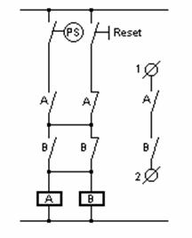
A
relay is almost fail-safe since it is very likely to brake the
circuit when it is malfunctioning. However, using two relays will
increase the reliability considerably. This can be done in different
ways. One method is to wire the relays, A and B, as shown on the
picture.
The system cannot be reset unless the pressure switch
(PS) makes and both relays work correctly, but the circuit between
terminal 1 and 2 will break when PS breaks even if only one relay
works rightly.
How
to make a computerized control system fail-safe
An output from a
computer will become either high or low when it fails. There are some
methods using the computer to check its own outputs. Feeding back an
output’s signal to an input will enable the computer to check
if the output is what it is supposed to be, but the system as a whole
will not be fail-safe. The CPU or any other vital part might break
down and then the check of the outputs is out of order.
The only
way to make a computer system fail-safe is to use an other computer
to check all the functions. It is, of course, possible to check all
the functions by means of hard wiring and relays, but who wants to do
that?
Pressure jet atomizer
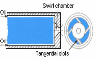
The
pressure jet atomizer utilizes the supply pressure energy to atomize
the fuel into a spray of finely dispersed droplets. Provided adequate
fuel pressure is used, extremely good combustion results can be
achieved.
The fuel oil is fed into the swirl chamber by means of
the tangential ports in the main atomizer body. An air core is set up
due to the vortex formed in the swirl chamber; this results in the
fuel leaving the final orifice as a thin annular film. This film of
fuel has angular as well as axial velocity causing the fuel to
develop into a hollow con as it discharges from the orifice.
This
type of atomizer has a poor turn down ratio. A small drop in
atomizing pressure will result in a dramatic reduction in combustion
performance. Two or three nozzles are sometimes fitted to achieve
turn down, one in use on low fire, two on medium fire and three for
full rate firing. A variation of the pressure jet atomizer is spill
return or recirculating burner. The problems with this type of burner
are that the atomizer has an increasing cone angle of the issuing
spray as the burner is turned down with impingement on the furnace
walls, being made possible and the additional problem of how to
dispose of the returned hot oil if the burner has been running for
prolonged periods on low fire.
External mix steam atomizer or Steam-assisted pressure jet atomizer
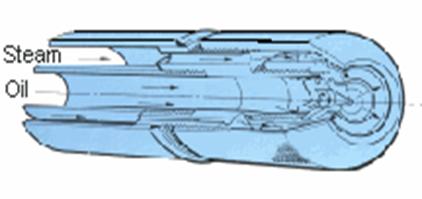
The
steam-assisted pressure jet atomizer is designed to make full use of
pressure jet atomization at high outputs and full use of blast
atomization at low outputs.
The atomizer consists of a
conventional simplex type of pressure jet tip, around which is
provided steam supply passage. Steam issues through an annular gap
after being provided with the correct degree of swirl to ensure that
the steam-exit angle matches the oil-spray cone angle. The
steam-supply pressure remains constant throughout the complete
turndown range of the burner. No mixing of fuel oil and steam occurs
within the burner-gun and hence oil o~tput is unaffected by slight
variations in the steam pressure.
Internal mix steam atomizer
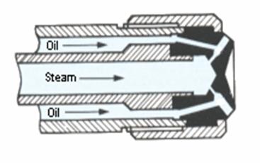
The
burner lance consists of two concentric tubes, a one-piece nozzle and
a sealing nut. The media supplies are arranged so that the steam is
supplied down the center tube and the fuel oil through the outer
tube. Consequently, the steam space is completely isolated from the
oil space.
The steam atomizer consists of an atomizer body that
has a number of discharge nozzles arranged on a pitch circle in such
a way that each oil bore meets a corresponding steam bore in a point
of intersection. Oil and steam (air) mix internally forming an
emulsion of oil and steam at high pressure. The expansion of this
mixture as it issues from the final orifice produces a spray of
finely atomized oil.
Oil burners with steam atomizing are
tolerant to viscosity changes. In addition to this advantage, the
steam atomized oil burners have better turn down, do not require high
fuel oil pump pressures, and are frugal in the use of steam.
Rotary cup atomizer
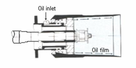
The
rotary cup is driven at high speed (about 5000 RPM) by an electric
motor via a heavy-duty belt drive. The fuel oil flows at low pressure
into the conical spinning cup where it distributes uniformly on the
inner surface and throws off the cup rim as a very fine oil film. A
primary air fan discharges the primary air concentrically around the
cup, strikes the oil film at high velocity and atomizing it into tiny
droplets.The rotary cup burner finds considerable use on packaged
shell type boilers. These burners have good turn down ratio and they
are rather insensitive to pollutants in the fuel oil.
Low pressure air atomizer
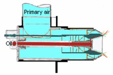
The
principle is similar to that of the rotary-cup-atomizer, but the fuel
is forced to rotate in a fixed cup by means of a forcefully rotating
primary airflow. Their general construction makes them suitable for
firing into chambers of hot brickwork, avoiding all the hazards of
back radiation to oil burners of more delicate construction. Low
pressure air atomizers imply air pressure up to 100 mbar (40 ins.
WG.).
Blue flame burner
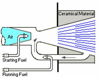
A
few words about firing sludge in a boiler furnace.
Is
the sludge a waste just to get rid of or is it a valuable fuel?
Well,
it’s both. It’s waste oil that you want to get rid of,
but it contains energy that you ought to utilize.
The waste oil
has to be conditioned to form a smooth emulsion with between 20% and
30% of water. Circulating the content of the sludge service tank with
a large pump and, if necessary, add some water will be a useful
method. The percentage of water might be measured by means of a
capacitive electrode in the pipe downstream the circulation pump. The
measuring method has some disadvantages, but it works.
The
temperature of the emulsion should be adjusted to achieve the
viscosity recommended by the burner maker, but it mustn't exceed the
boiling point of the water.
It’s normally difficult to
fire pure sludge; it has to be mixed with normal fuel oil. The
sludge/fuel oil ratio depends on the sludge quality. With a really
poor sludge you can only fire about 10% sludge. With a better,
well-mixed sludge the ratio could be much higher, but the burner has
to be continuously supervised, since it’s very difficult to get
a homogeneous sludge-mixture and the air demand may change
suddenly.
There is no problem to fire sludge with this method.
The problem is that sludge contains a great portion of ash and
nonburnable sediments that accumulates on the surfaces of the
furnace.
Increased soot-cleaning is strongly advised.
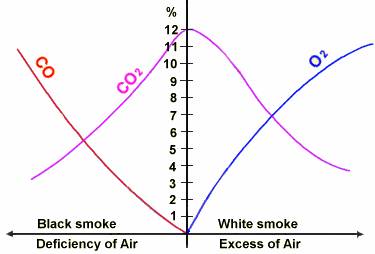
It is very easy to achieve a smokeless fire without any special equipment for supervision. On the other hand, to achieve a smokeless fire and economic combustion will be a bit harder. The air supply has to be slightly in excess of the theoretical requirements. That is, the combustion air flow is reduced almost to the smoke limit. A plant that never shows traces of smoke at the chimney is not burning the fuel efficiently.
There are four instruments that will help you to achieve the optimal combustion:
1. Smoke Density Monitor. High smoke density indicates uneconomical combustion and it might also cause penalty from the environmental protecting authorities.
2. O2 - Analyzer. High O2 content indicates heating of unnecessary high quantity of combustion air.
3. CO - Analyzer. High CO content indicates unburned hydrocarbons. This is not only uneconomical, the CO is also harmful to mans health. Besides, mixed with air, CO might be an explosion risk.
4. CO2 - Analyzer. Low CO2 content indicates poor combustion, but it doesn’t tell if more or less air is required.
The
most important instrument, the Smoke Density Monitor, happened to be
the cheapest of them and you can’t do without it if you are
trying to optimize the combustion of your burners.
The equipment
is very simple. A light beam is sent across the flue duct, from a
light emitter to a light receiver. An electronic unit monitors the
opacity. It indicates 0% if there is no black smoke present and 100%
if the light beam is totally absorbed by the smoke. An alarm
activates if the smoke density exceeds the preset limit.
Some advises:
The smoke density meters light emitter and light receiver are normally scavenged by sealing air to keep them free from soot. Therefore it would be vise to install these units higher up in the flue duct than the O2-analyzer to prevent the measured O2 value from being influenced by the smoke density meters sealing air flow.
Check and clean the glasses of the smoke density meters light emitter and the light receiver regularly.
The smoke density alarm should be overridden during the burners start and stop sequences, since the opacity normally increases before the flame has stabilized.
Never adjust the O2 content all the way down to zero unless you have facilities to check the CO content.
It might be worthwhile to spend a few minutes studying the diagram below.
|
|
Maximal velocity in pipes |
||||||||
|
|
Water |
m/s |
ft/s |
||||||
|
|
Tap water (low noise) |
0.5 - 0.7 |
1.6 -8.2 |
||||||
|
|
Tap water |
1.0 - 2.5 |
3.3 - 8.2 |
||||||
|
|
Cooling water |
1.5 - 2.5 |
4.9 - 8.2 |
||||||
|
|
Boiler feed water. suction |
0.5 - 1.0 |
1.6 - 3.3 |
||||||
|
|
Boiler feed water. discharge |
1.5 - 2.5 |
4.9 - 8.2 |
||||||
|
|
Condensate |
1.0 - 2.0 |
3.3 - 6.5 |
||||||
|
|
Heating circulation |
1.0 - 3.0 |
3.3 - 9.8 |
||||||
|
|
Lower velocity in thin lines. higher in thick lines. The pressure drop normally calculates separately for longer lines with several separate bend-resistance´s. |
||||||||
|
|
Steam |
m/s |
ft/s |
||||||
|
|
Saturated Steam. high pressure |
25 - 40 |
82 - 131 |
||||||
|
|
Saturated Steam. in special cases |
- 60 |
- 197 |
||||||
|
|
Saturated Steam. medium and low pressure |
30-40 |
99 - 131 |
||||||
|
|
Saturated Steam. at peak load |
- 50 |
- 164 |
||||||
|
|
Steam / Water emulsion |
- 25 |
- 82 |
||||||
|
|
The pressure drop normally calculates separately for longer lines with several separate bend-resistance's. |
||||||||
|
|
Oil |
m/s |
ft/s |
||||||
|
|
Suction lines for pumps |
- 0.5 |
-1.6 |
||||||
|
|
Suction lines for pump (low pressure) |
0.1 - 0.2 |
0.3 - 0.65 |
||||||
|
|
Discharge line for booster pump |
1.0 - 2.0 |
3.3 - 6.5 |
||||||
|
|
Discharge line for burner pump |
- 1.0 |
- 3.3 |
||||||
|
|
Air |
m/s |
ft/s |
||||||
|
|
Combustion air ducts |
12 - 20 |
40 - 66 |
||||||
|
|
Air inlet to boiler room |
1 - 3 |
3.3 - 9.8 |
||||||
|
|
Warm air for house heating |
0.8 - 1.0 |
2.6 - 3.3 |
||||||
|
|
Vacuum cleaning pipe |
8 - 15 |
26 - 49 |
||||||
|
|
Compressed air pipe |
20 - 30 |
66 - 98 |
||||||
|
|
Ventilation ducts (hospitals) |
1.8 - 4 |
5.9 - 13 |
||||||
|
|
Ventilation ducts (office buildings) |
2.0 - 4.5 |
6.5 - 15 |
||||||
|
|
Exhaust gas |
m/s |
ft/s |
||||||
|
|
Ducts at minimum load |
- 4.0 |
- 13 |
||||||
|
|
Stack at minimum load |
- 5.0 |
- 16 |
||||||
|
|
Boiler with one-step burner (on - off) |
5.0 - 8.0 |
16 - 26 |
||||||
|
|
Boiler with two-step burner (high - low) |
10 - 15 |
31 - 49 |
||||||
|
|
Boiler with modulating burner (3:1) |
15 - 25 |
49 - 82 |
||||||
|
|
To keep the surface free from soot the velocity should always exceed |
3.0 - 4.0 |
9.8 - 13 |
||||||
|
It is recommended that the maximum inlet velocities applied to control valves should be as shown in the tables below. |
|
||||||||
|
Globe Valves Size |
Liquid |
Steam or Gas |
|
||||||
|
mm |
inch |
m/s |
ft/s |
m/s |
ft/s |
|
|||
|
15 - 25 |
1/2 - 1 |
9 |
30 |
120 |
400 |
|
|||
|
40 - 50 |
1 1/2 - 2 |
7.5 |
25 |
90 |
300 |
|
|||
|
65 - 100 |
2 1/2 - 4 |
6 |
20 |
75 |
250 |
|
|||
|
150 - 200 |
6 - 8 |
6 |
20 |
70 |
225 |
|
|||
|
250 - 400 |
10 - 16 |
4.5 |
15 |
55 |
175 |
|
|||
|
Angle Valves Size |
Liquid |
Steam or Gas |
|
||||||
|
mm |
inch |
m/s |
ft/s |
m/s |
ft/s |
|
|||
|
15 - 25 |
1/2 - 1 |
13.5 |
45 |
135 |
450 |
|
|||
|
40 - 50 |
1 1/2 - 2 |
12 |
40 |
105 |
350 |
|
|||
|
65 - 100 |
2 1/2 - 4 |
10.5 |
35 |
90 |
300 |
|
|||
|
150 - 200 |
6 - 8 |
9 |
30 |
85 |
275 |
|
|||
|
250 - 400 |
10 - 16 |
7.5 |
25 |
70 |
225 |
|
|||
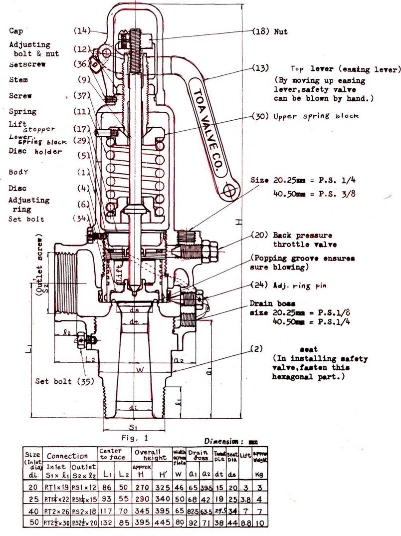
EXPLANATION OF OPERATION
This Type 1627 Full-Bore Safety Valve with its flat seat and piston type disc features its high relieving capacity.
A safety valve is required to blow off with utmost accuracy and sure-ness when the specified pressure ( mentioned on name plate) has been reached.
The relieving mechanism of this safety valve is characterized by the popping groove provided on the disc which produces an extra lift and also the adjusting ring for better utilization of the dynamic pressure produced by steam flow and hence the valve readily pops (opens quick and clear) once the specified blow-off pressure has been reached. The valve is also provided with a readily adjustable back pressure throttle valve which may be set to ensure secure closing of the valve after well-stabilized relieving of excess pressure. (Ref. Fig. 1 and 2.)
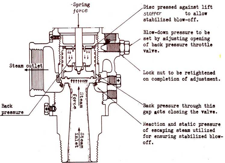
Fig. 2
Installation of exhaust pipe
With safety valves of full-bore type, proper arrangement of exhaust pipe is of particular importance. Care must be exercised to ensure secure fixing of the pipe to the valve. Standard piping plans recommended for our models are shown in Fig. 3 and Fig. k.
Hydraulic test gag
When a boiler is subjected to hydraulic test, it is always advisable to have the safety valves removed and blind covers fitted, for experience shows that the stem of the valve could be belt as it is kept pressed down during the test or dust or other foreign matters could find their way into the valve during the test to remain caught over seat face, thus interfering with proper functioning of the valve.
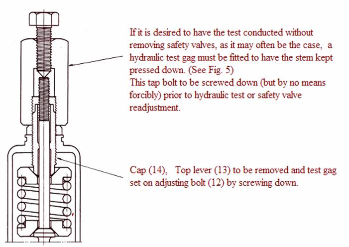
Since the disc of safety valve is pressed down under specific spring load corresponding to the specified blow-off or popping pressure, a very small application of force may be sufficient to have the valve locked against the hydraulic test pressure. It is always advisable to fasten the gag slightly after the test pressure has reached 80-90$ of the safety valve popping pressure and remove the gag after the test pressure has come down below the popping pressure.
In case more than two safety valves of different popping pressure settings are set on a boiler, the gag is to be used to lock the one with the lowest or lower poppint pressure.
Accidental blow-off of safety valve during adjustment can be hazardous and hence prior to adjustment it is essential to have the boiler pressure brought down to 80-90 % of the specified popping pressure and, if possible, the stem pressed down with test gag.
A. Adjustment of popping pressure
This is normally superfluous, for our valves are delivered precisely adjusted to the pressure specified on the name plate.
B. The data below may serve as guide for finding the number of turns to the adjusting bolt required for adjustment of popping pressure, to the desired level.
|
Safety valve size mm |
20 |
25 |
40 |
50 |
|
Adj. bolt 1\2 turn |
12.5 % |
10 % |
7.5 % |
5 % |
|
|| 1 turn |
25 % |
20 % |
15 % |
10 % |
It may be understood that the extent of such readjustment normally should not exceed +,- 10% of the value specified on the name plate. In case readjustment beyond this limit is considered essential, please consult us. (Major readjustments far beyond the said limit might call for replacement of the spring.)
C. Adjustment of closing pressure
With this safety valve, the extent of blow-down pressure (difference between poppint pressure and closing pressure) is adjusted a little broader than specified on the name plate but since the effective value is subject to change according to the way it is installed etc., adjustment in this respect has to be done on the spot. This, however, can be accomplished with ease by readjustment of the back pressure throttle valve, if the closing pressure of the valve not below 1.5 kg/cm2.
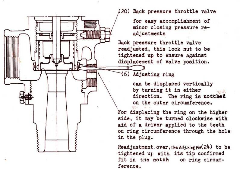
Fig. 6
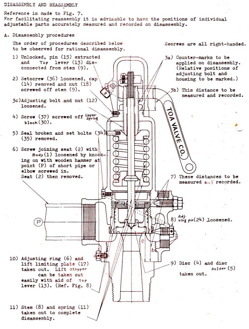
Fig, 7
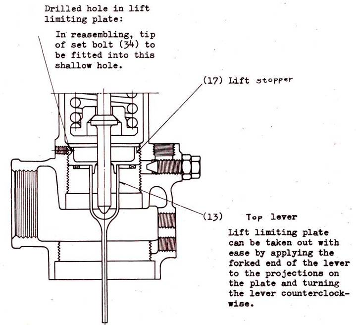
Fig. 8
B. Reassembly
For reassembly may be simply reversed the procedures given for disassembly.
Prior to reassembly, all parts to be thoroughly cleaned and repaired. Stem tip, spring shoe, spring clamp and stem-adjusting bolt contact face to be coated with molybdenum disulfide or graphite (dissolved in mineral oil) for lubrication. Recorded positions of lift limiting plate, adjusting ring, adjusting bolt etc. to be carefully observed in reasembling.
5. LAPPING AND REPAIR
The disc and seat of this safety valve can be easily lapped on a lapping plate with use of a proper type of lapping compound. As lapping compound is to be chosen # 600 kneaded with purified rape oil ("shirashimeyu") to non-flowing consistency. Hints on lapping:
1. Both lapping plate and parts to be kept clean.
2. Excessive application of compound to be avoided.
3. Lapping to be performed with lapping plate or disc in an alternate turning motion and pressed on lightly.
4. Lapping plate be precisely finished and kept well repaired.
5. Lapping of disc against seat to be avoided.
Practically, this valve calls for no repair work beyond lapping on the part of users and should there be any parts calling for repair, our service department is to be commanded or such parts mailed to us.
WATER LEVEL GAUGE (REFLEX TYPE)
INSTRUCTION MANUAL
TYPE RZ .
1. This water level gauge (reflex type) is usually sent out from our factory in the following packages:
1) Water level gauge (with lower cap nut)
2) Upper cock, lower cock and drain cock
(The drain cock is set with the lower cock.)
3) Marine parts: Wires
Wire parts (shackles, wire courses and wire clips)
Handles (6 handles)
Handle stoppers (to be mounted to the cock flanges)
4) Spares : Water level gauge
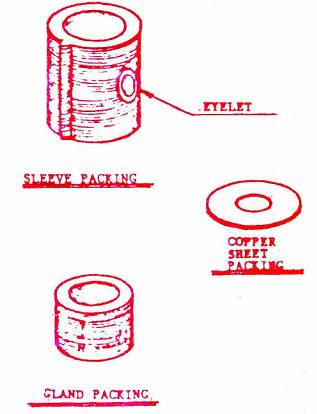
Gauge glass (with gasket)
Sleeve packings
Gland packings
Copper sheet packings (for only the lower lead pipe)
5) Tool : Sleeve packing replacing tool
Water Tightness Test before Operation
When this instrument is mounted for a newly installed boiler or a boiler in shutdown, carry out the following water tightness test for the water level gauge including the gauge cocks at the time of the boiler starting test.
1) Open the drain cock and close the upper and lower cocks. First, check the gas tightness of the upper and lower cocks (especially the opening and closing elements).
2) Next, close the drain cock and open the upper and lower cocks. Make the tightness checks for the whole of the water level gauge and cocks.
3) If any leakage is found in the test, take the corrective actions.
Precautions for Operation
1) In the water level gauge come from factory, there is a balance kept between the bolt tightening force and the gas tightness of each part by the hydraulic test under the ordinary temperature. Therefore, when this instrument is installed to the boiler in operation and also when the pressure and temperature are raised from the ordinary conditions along with the boiler pressure increase, take care to avoid a rapid pressure and temperature application to the water level gauge.
2) In operation and in pressure raise, use caution to find out leakage. Give a tightening to the bolt and nut of the part where any leakage occurs. Also after the pressure is raised to the specified value, check for any leakage. Even if there is no leakage, give a slight tightening to each bolt of the water level gauge.
3) At the start-up of the boiler, repeat water blowing until clean water is recognized so that the good conditions for the water level gauge will be kept in the boiler system. During operation, except when the water is polluted, water blowing is not desirable so far as the water level is fluctuating.
4) When the boiler is in operation, always make a leakage check and give a tightening when necessary. Thus, parts consumption must be minimized.
Maintenance
Disassembly and Reassembly of Water Level Gauge
After the lapse of the service life, the prism surface of the reflex type gauge glass wears out and loses reflectivity and as a result the water level becomes invisible. As the gauge glass and sheet packings are damaged, it becomes impossible to stop leakage with tightening of the water level gauge bolts and nuts. In such a case, disassemble the water level gauge and replace the worn-out parts in the following procedure:
1) Detach the water level gauge from the upper and lower cocks. Disassemble the water level gauge preferably when it is still in hot condition (this will facilitate the removal of the packings).
2) Place the water level gauge on a working bench, loosen the bolts and nuts and remove the cover.
3) As the gauge glass is sticking to the level gauge body through packings, slightly rap the side with a wooden hammer to remove the glass. If this disassembly is made in an early time, the gauge glass may be re-used if only the packings are replaced. In such a case, therefore, remove the glass carefully not to break it.
4) Remove the packings carefully not to damage the gas tightness of the water level gauge body (the surface of contact with the packings) Clean out the residual dirts.
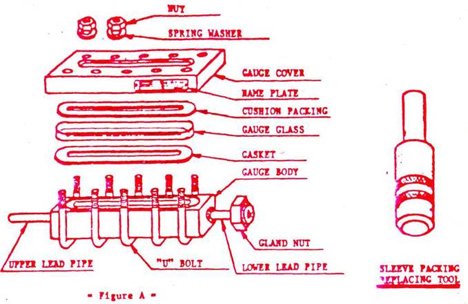
For the reassembly of the water level gauge, the above procedure is to be reversed. Follow the below instructions, referring to Figure A.
1) Attach the sheet packing to the gas tight surface of the water level gauge, using the following precautions:
a. Be sure to apply graphite paste to both sides of the sheet packing. It will facilitate the removal of the packing when gauge is disassembled.
b. As the sheet packing is hollowed out in the center part, it is likely to deform to narrow the cut-out area. When the packing is placed, care should be taken to keep the specified level gauge window area.
2) On the sheet packing, place the gauge glass with the prism side directed toward the liquid chamber.
3) Then, attach the cushion packing (asbestos plate) to the gauge cover and connect the gauge cover to the gauge glass. For setting the gauge cover, set the U bolt at the center to fix the cover temporarily and then set the other U bolts. As there is some allowance between the gauge glass and glass groove, carefully center the cover, gauge glass, and water level gauge body.
4) For tightening the bolts and nuts, follow the instructions.
Tightening of Level Gauge Bolts and Nuts
Troubles such as gauge glass breakage and early-time leakage from the gauge glass in boiler operation are said to be, in most cases, caused by uneven tightening of bolts and nuts in reassembly of the level gauge, This means that the tightening of the bolts and nuts is the most important of various water level gauge maintenance works. Follow the below instructions:
1) Note that the water level gauge contains glass-ware and it belongs to delicate measuring instruments. Therefore, the tightening of the bolts and nuts must be made with the utmost care.
2) Set all the bolts and nuts hand-tight with an even torque. It is important to tighten them suitably to the extent that leakage can be prevented. Avoid uneven tightening.
3) Tightening is to be repeated several times with light hand motion as follows: For the first and second tightening, follow the numerical order given in the below sketch (the order from the center to the ends). For the third and fourth tightening, reverse the numerical order (i.e. from the ends to the center).
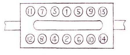
4) For the fifth and sixth tightening, again follow the numerical order (i.e. from the center to the ends).
5) In the last tightening, leave some tightening allowance by saving the hand force. If any leakage is found after the level gauge has been placed in service, give an additional tightening in the manner specified above.
6) In reassembly, too strong tightening can cause the gauge cover to bend or cause the gauge glass to break due to pressure application heat expansion in service.
7) In the last tightening, take case so that the tightening torque of the uppermost and lowermost bolts (4 bolts) will be kept at half the torque of the other intermediate bolts. The reason is that, as seen in the sketch, the uppermost and lowermost bolts (4 bolts) are located outside the gauge glass and, therefore, too strong tightening may cause the glass ends to break when the gauge is placed in service.
Additional Tightening and Replacement of Sleeve Packings
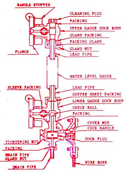
When the inside surfaces of the sleeve packings wear out with the cock plug opening and closing motion, leakage will occur from the cover nut or tightening nut (shown in Figure B). In such a case, give an additional tightening or replace the packings in accordance with the following instructions :
1) Tighten the tightening nut. The sleeve packings will be pressed toward the cock plug so as to recover the gas tightness and stop the leakage.
2) Every time when leakage is found, immediately give an additional tightening.
3) If such an additional tightening cannot stop the leakage, it indicates the loss of elastivity of the packings. Replace the sleeve packings, following the below procedure:
a. Remove the handle, tightening nut and cover nut.
b. Extract the cock plug toward the handle side. If it cannot be extracted by hand, apply an iron bar of about 10mm in length to the bottom of the cock plug and rap the bar to extract it out.
c. Then, apply the sleeve packing replacing tool (shown in Figure C) to the bottom of the packings. Rap out the packings toward the handle side.
d. For insertion of new sleeve packings, use the sleeve packing replacing tool and drive the packings into the cock body from the handle side.
e. Put the packing boss just in the groove of the cock body and insert the packings so that the periphery of the packings will be located at the position 11mm deep from the cock body periphery.
f. Mount the cover nut, and keep a clearance of about lmm between the cover nut and cock body.
g. Then, the cock plug is inserted. Apply the iron bar (indicated in Item b above) to the bottom of the cock and drive in.
h. Mount the cover nut and tightening nut.
i. Mount the handling.
j. Make an air (or water) passage test.
Replacement of Gland Packings
When the cap nut tightening cannot stop the leakage from the gauge cock and level gauge connecting part, replace the gland packings, following the below instructions:
1) Remove the upper and lower cap nuts and packing gland, and push up the gland packing.
2) Disconnect the lower lead pipe from the lower cock, and extract the upper lead pipe.
3) Smash the gland packings with use of a chisel, and remove them completely. Clean the stuffing box.
4) Drive in new gland packings to the position just lower than the specified position of the upper lead pipe. Then, plunge the upper lead pipe into the upper cock.
5) Gland packings must be replaced every time when the water level gauge is disassembled. However, copper packings can be re-used after they are annealed.
6) Then, carefully drive the gland packings into the stuffing box and mount the packing gland and upper cap nut.
7) Tighten the cap nuts in the order of the lower cap nut and upper cap nut.
Other Precautions
At periodical maintenance, disassemble the water level gauge and carry out the replacement of consumables and the cleaning of the gas (water) passage holes. Apply graphite paste to each threaded part before reassembly. Check the gas tight surface of the water level gauge for any distortion or erosion. When necessary, repair or replace them.
