CARE OF PROPELLERS
Inspection by ship's engineer. Whenever a ship is docked, one of the ship's
engineers should examine the propellers, and the result of the examination
should be entered in the engineering log.
Inspection by yard force. As soon as practicable after docking a
vessel, the yard force should make a careful examination of the propellers, and
any repairs found necessary should be immediately undertaken, so that the
undocking of the vessel will not be delayed. (For sample inspection data
requirements, see Fig. 15A, B & C.)
Data on propeller hubs. The following data should be clearly stamped
in a conspicuous place other than the blades:
A. B. S. Approval Manufacturer's Number
Name of Ship
Builder
Owner's Approval
Plan Number
Finished Weight, lb.
"Port" or "Starboard" if twin screw
Diameter
Face Pitch (at 0.7 rad.)
Also the number of each
blade should be stamped on the hub next to that blade.
Verify data. The heat
number and builder's name stamped on the hub should be verified and recorded
upon each removal at docking. Adjustments made, general conditions found and
work performed should be recorded in the engineering records of the vessel.
When the propeller is removed, the condition of the propeller nut and locking device should be inspected and should be checked again before the fairwater cap is replaced.
Make a report of all
inspection, repairs to or changes of propellers installed on ships, hub data,
pitch measurements and balancing data.
Cleaning
propellers.
Fouling
or even slight damage to a propeller has a marked influence on the frictional
resistance, and results in an increase of horsepower over that necessary to
deliver the same number of revolutions with a clean or undamaged propeller.
Propellers may be cleaned by the ship's force when the vessel is in dry
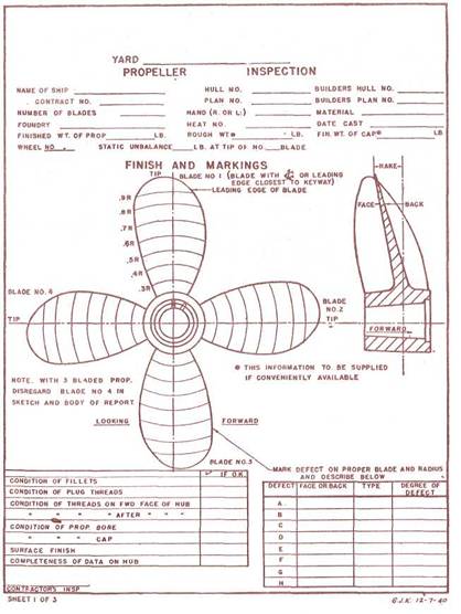
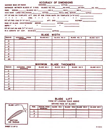
Fig.
15A. Sample inspection data
sheet Fig. 15C. Inspection data sheet continued
dock or on a marine railway, or by divers when
the vessel is in the water. When the fouling rate may have been appreciable due
to inactivity of the vessel or to water conditions, propellers should be
cleaned prior to extensive operations.
After docking it may be necessary to remove barnacles by scraping
and wire brushing.
After cleaning bronze propellers, give them a final polishing with a
fine abrasive. Then give them a coat of lubricating oil. Do not apply paint.
Faulty and damaged sections, of bronze propellers,
if not too extensive, may be cut out and then rebuilt by use of bronze welding.
Pits and rough portions of cast-iron propellers or cast-iron
fairwater caps should be thoroughly cleaned and filled with iron cement before being painted. Apply the
same quality of paint and number of coats that are used in painting the ship's
bottom.
Care of shaft taper. Most failures of tail shafts
occur at the large end of the taper just abaft the bronze shaft sleeve, under
the propeller hub. To make sure that salt water will not enter this dangerous
region, rubber rings are provided in the propeller gland, and the space aft of
the rubber rings is filled with a mixture of white and red lead and linseed
oil. When the propeller is removed the shaft taper, including the keyway,
should be carefully examined for corrosion or cracks. If the rubber rings have
deteriorated they should be replaced. The propeller may not be replaced
without the approval of the American Bureau Inspector.
PRECAUTIONS TO
MAINTAIN PROPER
PITCH OF PROPELLER AND DIMENSIONAL CHARACTERISTICS OF BLADES
Pitch. To preserve the pitch of a propeller the
shape and setting of blades must always correspond to the specifications for
the propeller.
Square mark.
All removable blades have a square mark to register
with a corresponding mark on the hub. Coincidence of these marks proves a blade
to be properly set and the pitch to be correct unless the blade has been bent.
Should it be desired to prove the pitch of a propeller, a pitch-ometer is used. Repair yards are equipped with instruments
suitable for the purpose.
Pitchometer.
Should it be necessary to
improvise a pitchometer, proceed as follows:
If the pitchometer is to be used with the
propeller in place, remove the cap and the propeller nut, and make a block with
counterbore to fit neatly over the threads of the
propeller shaft. If it is to be used after the propeller has been removed,
provide a wooden plug to fit the bore of the propeller. Pivot a stiff,
straight, wooden batten to the after end of the block at a point corresponding
to the center of the shaft. The batten must revolve in a plane at right angles
to the axis of the shaft. At intervals of 6 or 12 in. along the batten nail
small wooden strips for guiding a graduated pointer. These strips must be
secured as nearly as possible parallel to the axis of the shaft. A pointer
graduated in inches and fractions thereof and a paper protractor graduated in
increments of 5° complete the apparatus. The paper protractor is pasted on the
after end of the block.
Obtaining the pitch.
In obtaining the pitch of a
propeller three measurements are necessary:
The radius at which the pitch is measured.
The angle or part of the complete circumference
corresponding to the distance on the blade between the two points between which
the pitch is required.
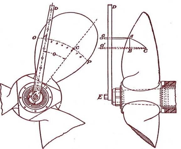
Fig. 16.
The advance parallel to the
shaft line, corresponding to this part of a complete revolution. (Note: The advance in inches for an arc of
30° is equal to the total pitch in feet.)
These measurements are obtained by means of the pitchometer
as follows:
With a radius EA' = R on
batten ED draw the arc OP, using graduated pointer AG. (See Fig. 16.) Select
two points, A and C, such that the angle
AEC = 0 is any multiple of 5° measured on the
protractor F. By means of the graduated pointer measure the distances AA' and
CC. The difference between these measurements (BC) is the advance
corresponding to the angle 6. Since in a complete revolution the point A
travels a distance equal to the whole pitch, and for the angle 0, a measured
distance equal to CC" — AA', we have 360° whole pitch (P) :: angle 6 :
fraction of pitch (CC - AA'). Therefore
![]()
The number of points measured depends on the requirements of the
occasion.
Rough check on the pitch. A check on the pitch of an installed propeller
may be obtained by the following rough but fairly accurate method:
Turn the propeller to bring one of the blades horizontal. Select the
radius R at which the pitch is desired and hang a cord with two weights as
shown in Fig. 17. Care must be taken that the two points, A and B, at which the
cord touches the edges of the blade, are at the same distance from the center
of the propeller. It is then readily seen that the points A and B of Fig. 17
correspond to the points A and C of Fig. 16, except that in Fig. 17 they are
necessarily taken on the extreme edges of the blade. Level a batten PQ and
measure the distances AC and BC. The pitch for radius R is:
![]()
Balancing.
Propellers should not be dynamically balanced
unless specifically required. The material to be removed to effect static balance
may be taken from either the after (pressure) or forward (suction) faces of the
blades, but in those cases where the material is to be removed from forward
faces, special care should be exercised to maintain the designed curvature of. the blade section and to avoid humps and hollows. In those
cases where metal is removed from the after faces for the purpose of balancing
after the establishment of the finished surface for this face, the areas from
which the metal may be removed shall not approach the blade edges within 25% of
the blade width, care being exercised to avoid radical changes in thickness of
sections. The unbalance tolerance shall be based on a centrifugal force equal
to 1% of the weight of the propeller when revolving at its rated r.p.m. (The reason for balancing propeller is to aid in
eliminating vibration.)
Average pitch.
For repaired propellers the average pitch of any one blade shall not
vary more than plus or minus 1% from the average pitch of all blades, and the
average pitch of all blades shall not vary more than plus or minus 11\2 %
from the designed pitch. No individual element of the blade should vary over 2%
from the designed pitch.
Propeller blade thicknesses, and leading and trailing edge details,
shall be accurate within a tolerance limit of plus or minus 2% of all
variations in excess of 1/32 in. from the designed dimensions. This is for
propeller efficiency and to avoid vibration.
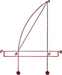
Fig. 17.
For checking the accuracy of the blade surfaces a straight edge can
be applied to the after face of constant pitch propellers and variable pitch
propellers, if the pitch variation is uniform along the blade generatrices. The uniformity of the forward face can be
checked by the use of a flexible steel straight edge which can be sprung across
the surface at various locations to detect humps and hollows.
Repair guide list.
When repairs are undertaken
in dock, it is essential that a thorough inspection be made so that all defects
may be found and remedied. Therefore a repair guide list is suggested for use.
Should an item be not done it should be so checked on the list, as often
information of a negative character is found valuable. Upon completion of work
the repair guide list should be preserved as a record of conditions found, data
taken, and work done. It will then be available for examination when the next
docking takes place, and the series of guide lists will form a complete
history, with minimum clerical effort.
Removal of wing propellers.
To take off a wing propeller proceed as follows:
a) Remove propeller nut.
b) Place a draw-bolt clamp or strong back over the end of the shaft.
c) Interpose a piece of soft metal between damp and shaft end,
if there is danger of upsetting threads on shaft.
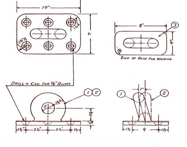
Fig. 18A. Pad eye for lifting propeller. (154" size—eye
2", pad 7" x 10" x 54").
d)Insert draw bolts in tapped holes in hub face if
provided. Otherwise hook the bolts over the blade edges or screw them into
pieces of metal laid across the forward edges of the blade roots.
e)
Arrange propeller rigging.
f)Set up on clamp nuts until propeller starts, or stress
is as great as clamp will stand.
Use a maul or a button set
judiciously.
g) If propeller will not start, heat must be applied to expand the
hub.
Removal of single-screw propellers.
To remove the propeller of a single screw ship with a balanced
rudder, remove rudder and then treat like a twin-screw ship. Otherwise the
following procedure will be necessary.
a) Break tail shaft and aftermost line shaft
coupling, and loosen up the
stern-tube glands.
b) Clear aftermost line shaft section.
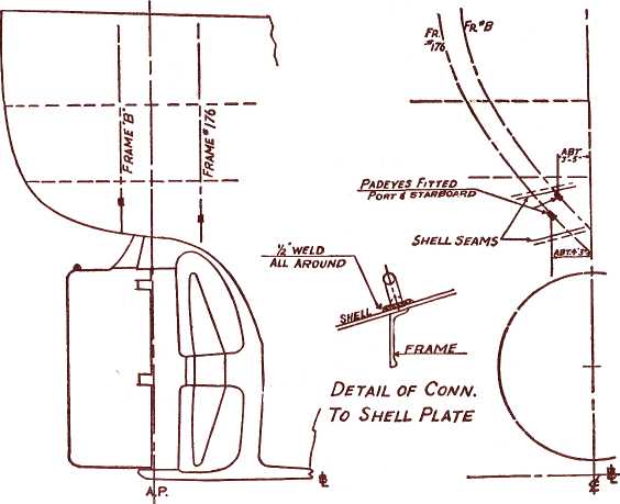
Fig. 18B.
Location of pad eyes for lifting propeller and
rudder.
c)Remove propeller fairwater cap.
d)Loosen and back off
propeller nut.
e)Place strong back in place and insert draw bolts,
placing a piece of copper or brass between the strong back and the shaft.
f) Adjust rigging.
g) Set up on the strong back until either the propeller starts or
the stress on the strong back is as great as desirable. Use a maul
judiciously.
h) If the propeller does not start, heat will have to be applied to
the hub. Care should be taken that steam is not formed in the cored hole in the
hub, as this has caused serious accidents.
i) After the propeller
starts the weight of the propeller is taken by chain hoists of adequate size,
and the tail shaft drawn inboard until clear.
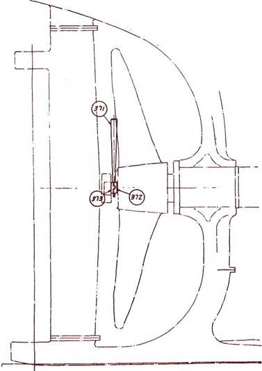
Fig. 19A. Installation of propeller,
using wedges.
Partial straightening of bent blades can be easily done. The method
used depends on the extent of the damage. Bends near the edge can be handled by
sledges and clamps. For more extensive bends special heavy clamps must be
rigged to take a strain from a chain fall. With a heavy strain on a clamp a
light blow on the blade at the proper place will frequently do considerable
straightening.
How to apply heat.
Heat is applied to a propeller by using preferably two large
burners, one on each side of the hub. If only one burner is available, work
the flame around the hub to heat and expand the metal uniformly. The largest
propeller can usually be heated sufficiently in about an hour with two burners.
Before applying heat, cover exposed parts of shaft near the
propeller with asbestos. Remove filling hole plugs in
the hub and hub cap and loosen all cover plates to permit escape of vapor.
In removing or replacing a
propeller nut, it is good practice to fit a shore from the bottom of the dock
to a propeller blade near the root, so that it will take the shock of driving
the propeller nut and prevent the shock of the blows being transmitted to
reduction gearing, rotors, or crank shaft.
Method of installing propeller of single-screw ship.
The wheel and tail shaft should be carefully checked. A thin coat of
white lead and lubricating oil or Houghton's Rust Veto should be applied to the
tail shaft taper. The propeller is set in position and held by a screw jack
against the rudder post. The tail shaft is pushed into the hub taper, using
chain falls in the shaft alley. After the wheel is installed on the shaft as
far as it will go, the propeller nut should also be driven as far as it will
go, always allowing room for stub wedges to drive wheel up in place. When wheel
is close up to counterbore, red lead putty is
inserted in the ( counterbore and then the
wheel is driven up as far as it wiH go with the use
of stub wedges. After the wheel is up as far as it will go, using stub wedges,
they should be removed and box wedges installed. The box wedges should be
driven up until the wedge sings. Then the boxes should be reset so there is
plenty of movement to drive the wedges (wedging up tail shaft from inside the
ship).
After the wedges are again set and in a singing position the old fit
mark should be observed to see how far the propeller should go up. After checking
this mark and seeing that everything is well protected, a
S-minute heat should be thrown on the wheel with two Hawk torches, one on each
side of the hub. After taking any chill out that may be in the wheel, the heat
should be stopped and orders given to the men to stand by the box wedges. When
wedges are again singing, a careful check should be made
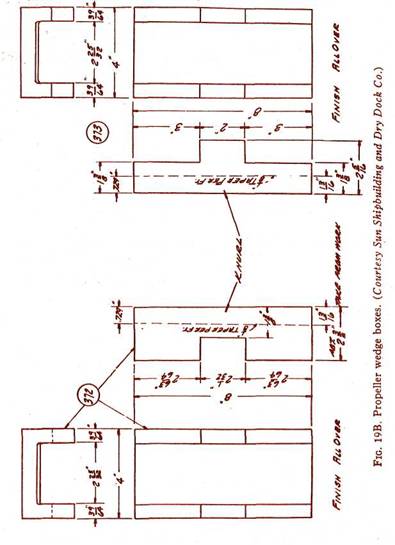
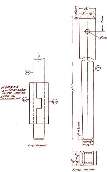
Fig. 19C. Propeller wedge assembly
and details.
to determine whether they are past the marks
installed on the shaft, in which case a new mark should be made. The boxes are
now removed, the thread cleaned and the nut tightened, using chain falls. The
keeper is installed and the hub cap fitted. The hub cap and the interior of the
propeller hub are filled with tallow, and the pipe plugs fitted and then
prick-punched to prevent backing out. Then the last section of the line shaft
is installed.
The rigging supporting the propeller while it is being fitted should
be carefully inspected and should be thoroughly adequate.
Extensive repairs.
Propellers, if appreciably damaged, should be repaired in a shop
rather than in place on the ship. When extensive propeller repairs are
contemplated or when repairs are of a nature which require machining or
chipping to restore to designed dimensions, a yard estimate should be obtained
before proceeding with the work, and approval of the A.B.S. and the Marine
Inspection Service of the U. S. Coast Guard must be had.
If a propeller blade is bent to the extent that it must be repaired
quickly so as to keep the vessel in service, and it is not possible to return
it to a qualified propeller manufacturer for repair, great care should be
exercised in the application of heat. At no time should the repaired section
be worked at a temperature higher than cherry red. As soon as this condition
changes to black heat, work should stop and the worked portion reheated.