THERMOSTATIC EXPANSION VALVE:
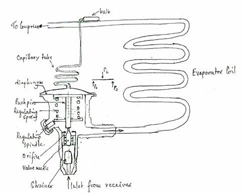
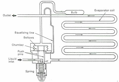
Thermostatic Expansion Valve controls the flow of refrigerant into the evaporator ensuring high heat transfer under varying load conditions, without allowing liquid to pass into the suction line and enter the compressor i.e. it is maintaining a constant degree of superheat at the evaporator outlet. It also maintains a pressure differential between the high and low pressure side of the system.

The thermostatic element, comprising the bulb and capillary tube, is usually charged with the same refrigerant as the system. For correct operation of the valve, the bulb must be securely clamped to the suction line. The operation of the thermostatic expansion valve is governed by the inter - action of three forces :-
(i) Pb, the bulb pressure on the upper side of the diaphragm, tending to open the valve, where Pb is the saturation pressure of the refrigerant in the bulb, corresponding to the temperaure of the gas.at the evaporator outlet.
(ii) Po, the evaporator pressure on the lower side of the diaphragm, tending to close the valve, where Po is the saturation pressure of the refrigerant at the evaporator inlet and DP is the pressure drop between the evaporator inlet and outlet.
(iii) Ps, the pressure exerted by the regulating spring, tending to close the valve. The spring tension, set by the regulating spindle, controls the degree of superheat, a typical superheat value is 4°C to 6°C.
At any constant operating condition, these forces are balanced and Pb = Po + Ps.

Thermostatic expansion valve connection
If the superheat starts to rise, that is starvation of gas flow, then the bulb pressure increases, Pb > Po + Ps, and the valve is moved in the.opening direction, admitting more liquid and restoring the normal operating condition. If the superheat falls, Pb < Po + Ps, i.e. excess flow of refrigerant, then the valve is moved to the closing position, reducing the supply of liquid.
ELECTRONIC EXPANSION VALVE SYSTEM:

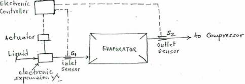
The system is designed to provide precise, rapid and remote control of the liquid supply to dry expansion evaporators, in response to the temperature difference between the evaporator outlet and inlet.
- The system comprises three main components : expansion valve with electric valve actuator, electronic controller and two plutonium 1000 temparature sensors. The expansion valve is opened and closed by the actuator. The actuator comprises a pressure reservoir, which holds a given amount of liquid, an electric heating element, and a negative temparature coefficient sensor. During normal operation the heating element keeps the liquid in the actuator at such a temparature and pressure, the stable equilibrium between the evaporator pressure under the diaphragm and pressure in the actuator, over the diaphragm is maintained.
OPERATION:
The measured temparature differential (S2 - S1) is compared in the controller with the required temparature differential (set value on the controller). If the measured valve deviates from the set valve, power to the heating element is changed to cool or heat the actuator. The pressure in the actuator changes, causing the valve to move in an opening or closing direction, increasing or restricting liquid refrigerant supply to restore the required temparature differential.
The proportional plus integral control of the controller ensures that the measured value (S2 - S1) does not deviate from the set valve on variations of load, evaporating pressure, sub - cooling and pressure drop across the expansion valve.