OILY WATER SEPARATOR
PRINCIPLE OF OPERATION
The main principle of separation by which commercially available oil/water separtors function is the gravity differential between oil and water.
In oil mixtures, the oil exists as a collection of globules of various sizes. The -acting on such a globule, causing it to move in the water is proportional to the difference in weight between the oil particles and a particle of water of equal volume-. This can be expressed as :
F
=![]() x
d3 x (fw -
fo )
g
x
d3 x (fw -
fo )
g
Where,
F = Separating force
fw = density of water
fo = density of oil
d = diameter of oil globule
g = accelaration due to gravity.
The resistance to the movement of the globule depends on its size and the viscosity of the fluids. For small particles moving under streamline flow condition, the relationship between these properties can be expressed by Stoke's Law :
Fr
= 3
![]() v
v
![]() d
d
Where,
F = Resistance to movement
![]() =
Viscosity of fluid
=
Viscosity of fluid
v= terminal velocity of particle
d = diameter of particle.
When separation of an oil globule in water is taking place, Fs will equal Fr, and the above equations can be worked out to express terminal velocity of the globule in terms of viscosity, relative density and particre size.
v
= (g\18![]() )
(fw- -
fo) d2
)
(fw- -
fo) d2
In general, a high rate of separations is encouraged by a large size of oil globule, elevated temperature of the system (which increases the specific gravity differential of the oil and water and reduces the viscosity of oil) and the use of sea water. Turbulence and agitation should be avoided since it causes mixing and re-entrainment of the oil. Laminar or streamlined flow is beneficial. *■
In addition to the heating coils provided to optimize separation, there are various other means used to improve and speed up operation. The entrance area in oil/water separators is made large so that flow is slow and large slugs of oil can move to the surface quickly. Low capacity pump encourages slow and laminar flow. Alteration of flow path in a vertical direction continually brings oil near to the surface, where separation, is enhanced by weirs which reduce liquid depth. Angled surfaces provide areas on which oil can accumulate and form globules, which then float upwards. Fine gauge screens are also used as coalescing or coagulating surfaces.
PUMPING CONSIDERATION:
A faster rate of separation is obtained with large size oil globules or slugs and any break up of oil globules in the oily feed to the separator is avoided. The type and rating of the pump for separator feed duty as well as pipe design are carefully selected to avoid turbulence due to sharp bends or constrictions. Pipe size and liquid flow are selected to ensure laminar flow.
Pump
suitability for oil/water separator
duty
Type
Remarks
Double Vane Triple Screw
Single Vane
Satisfactory at 50% de rating.
Rotary gear
Reciprocating
Hypocycloidal . Not satisfactory ; modification may improve
efficiency to 'satisfactory' level.
Diaphragm
Disc and Shoe
Centrifugal Unsatisfactory,
flexible vane


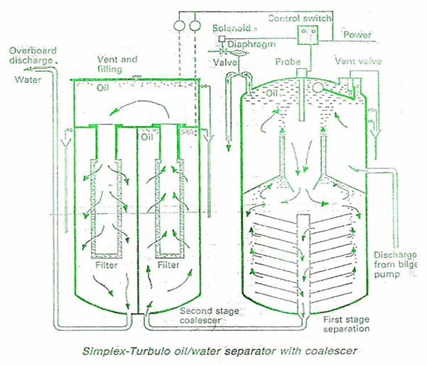
TURBO OIL/WATER SEPARATOR WITH COALESCER
It consists of three vessels which are initially filled with clean sea water. The 1st stage consists of a vertical cylindrical pressure vessel containing a number of inverted conical plates. The oily water is admitted to the 1st stage separator at the upper half and directed circumferentially around the shell in a horizontal plane to effect good distribution over the area of the vessel and then starts on a downward path to the conical plates. The majority of large globule free oil separate out in the upper part of the separator. The smaller globules are carried by the water into the spaces between conical plates at a control velocity which causes-the free oil droplets to coalesce and rise to the top and trapped underneath an annular baffle and is then led up through the turbulent inlet area by risers to collect in the dome of the separator. The water leaves the conical plate pack via a central pipe to the 2nd stage of the separator.
Oil is discharged from the 1st stage by a piston operated oil valve, which is motivated by a solenoid controlled pilot valve, which takes pressure from water discharge valve.
AUTOMATIC CONTROL OF OIL DISCHARGE
It is effected by means of a vertical capacitance probe in the top of 1st stage vessel, the probe being normally salt water finding. When oil completely surrounds the probe, altering its capacitance, it energises the solenoid of the pilot valve which in turn opens the oil valve. This causes a partial loss of pressure in the vessel and the water valve will close. On completion of oil discharge the capacitance of the probe will again alter to de-emergise the pilot valve solenoid and so close the oil valve, when the pressure will build up again and the water valve will open. An alarm probe is fitted to warn of an oil build up should the control system malfunction.
The water discharge from the 1st stage enters the 2nd stage at the bottom and passes vertically through a coalescer bed or filter. The coalesced up oil is removed from the top of the vessel and the water discharge to the 3rd stage.
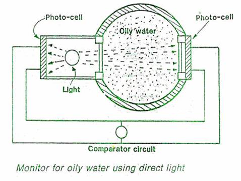
The 3rd stage is similar to the 2nd stage, where further coalscing takes place, oil goes on top and removed. The water discharge from this stage can be passed overboard after monitoring.