PRIMING :
A centrifugal pump placed above the liquid level to be pumped, is not self - priming, because it can not exhaust the air contained in its casing and suction pipe. So it must be placed below the level of liquid to be pumped or it must be provided with an external device for the removal -of air. Bilge pump or Ballast Pump (which may also be statutory bilge pump) must be of self- priming or equipped with a means of priming. Cargo pumps for oil tankers are likely to be arranged for stripping the maximum amount of liquid from tanks should be of positive displacement type (self priming).
AIR HANDLING METHODS:
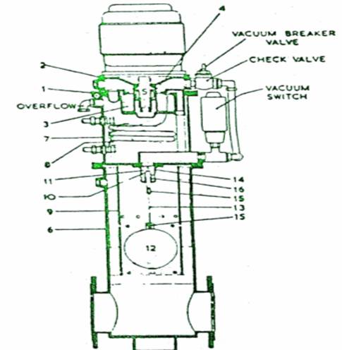
The removal of air from suction pipes is usually achieved with a liquid ring primer. This is necessary in order to produce vacuum conditions, so that atmoshpheric pressure on the surface of the liquid to be pumped will promote flow into and priming of the
pump.
The liquid ring air pump consists of a bladed circular rotor, shrouded on the underside, which rotates in an oval casing. Sealing water is drawn into the oval casing through a make-up supply pipe. The water, thrown out to the casing periphery by the turning rotor, whirls around, to form a moving layer against the oval casing. The water seals the rotor blades and also recedes from and re-approaches the rotor boss twice in each revolution. The effect is to produce a series of reciprocating water pistons between the blades.
As the water surface moves out from the rotor boss, it provides a suction stroke and as it moves in, a discharge stroke. The shaped suction and discharge ports, provided above the elliptical core formed by the rotating water, permit air to be drawn in from the main pump suction pipe float chamber and expelled through the discharge ports, to atmosphere.
A continuous supply of sealing water is circulated from the primer reservoir to the whirlpool casing, and discharged with the air back to the reservoir. The air passes to the atmosphere through the overflow pipe. This circulation ensures that a full water - ring is maintained and the cooling coil incorporated in the reservoir limits the temperature rise of the sealing water during long periods of operation. The supply for the cooling coil can be taken from any convenient sea - water connection. About 0.152 litres/sec at a pressure not exceeding 2 bar.
The rotary air pump is directly driven by an extension of the motor spindle on top of the pump.
The air handling capacity of water ring primer is good and the pump functions as a positive displacement pump.
FLOAT CHAMBER :
The water ring primer draws air from the pump suction pipe, through a float chamber. The float rises as liquid replaces air and as the level rises well above the pump, the impeller and casing are flooded and the float spindle closes off the suction. This ensures that the primer itself is not flooded.
GENERAL PURPOSE PUMPS :
Single entry general purpose pumps are used for salt and fresh water circulating purpose. A single impeller rotates in a casing of spiral or volute form mounted on stainless steel shaft. Fluid enters the impeller through the central eye and then by centrifugal action continues radially and discharges around the entire circumference. The fluid in passing through the impeller recieves energy from the vanes giving an increase of pressure and velocity. The kinetic (velocity) energy of the discharging fluid is partly converted to pressure energy by suitable design of impeller vanes and volute casing. In some pumps, e.g. turbine driven boiler feed pumps, diffusers are used, which consists of a ring of stationery guide vaves surrounding the impeller, the passage through the diffuser vanes further changes kinetic energy to pressure energy to give a high pressure delivery to enter the boiler.
Impeller is normally suspended from the shaft with no bottom support. A neck bush provides lateral location. There are renewable wear rings, usually of aluminium bronze, located .at the top and bottom around the collars or boss of the impeller. The clearance between the wear rings and collars is minimal to restrict the flow of liquid from the discharge side. A-short circuit flow would reduce efficiency and pressurize the shaft seal.
The performance of a centrifugal pump is dictated by speed of rotation, the impeller diameter and the area of the flow passage through the impeller width. The first two variables basically control the pressure generated and the last the quantity of liquid delivered.
In double inlet pumps fluid enters from two sides of the impeller eye as if there were two impellers back to back giving twice the discharge at a given head. In multi -stage pumps, the fluid from one impeller is discharged via suitable passage to the eye of

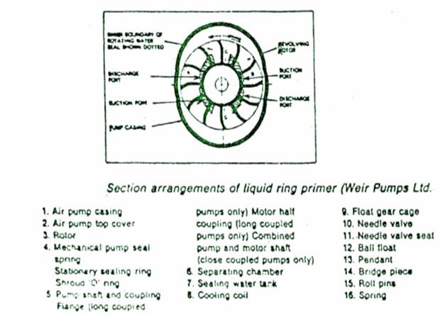
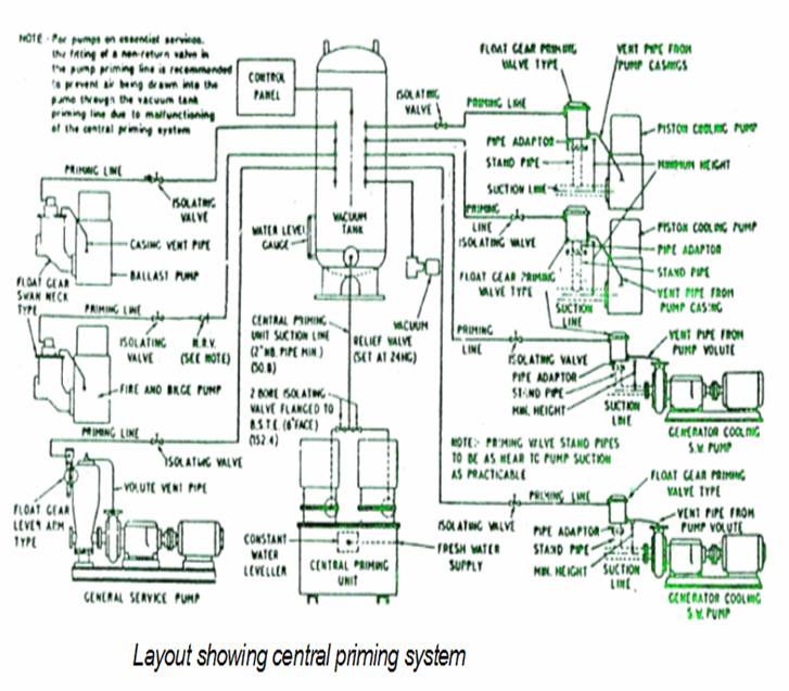
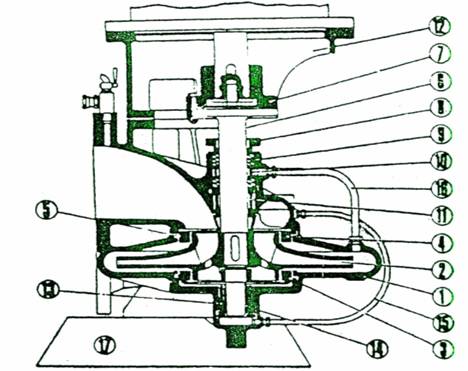
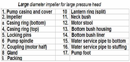
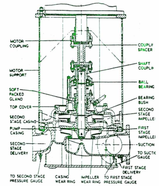
Fig A two-stage centrifugal pump, typical of a fire pump
the next impeller so that the total head developed (or discharge pressure) is the product of the head per stage and the number of stages. Thus at a given head a two - stage pump will give double the pressure. Such pump is often used for high pressure discharge at moderate speed (e.g. turbo - feed).