CENTRIFUGAL PUMP CHARACTERISTICS:
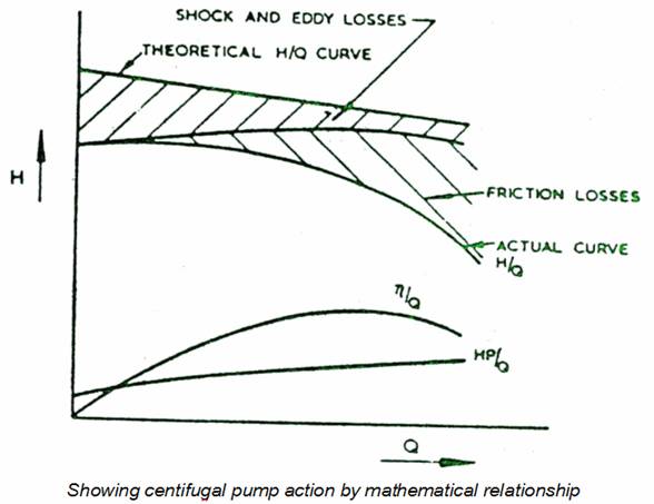
From a mathematical consideration of the action of a centrifugal pump, it can be shown that the theoretical relationship between head H, and throughput Q is a straight line with minimum throughput occuring when the head is maximum. Because of shock and eddy losses caused by impeller blade, thickness and other mechanical consideration there will some head loss, increasing slightly with throughput. These losses together with friction losses due to fluid contact with the pump casing and inlet and impact losses, result in the actual H/Q curve.
Unlike
the positive - displacement pumps, a centrifugal pump at constant
speed delivers any capacity from zero to a maximum value, depending
on the size, design and suction conditions of the pump. Total head
(H) developed, power (P) to drive the pump, and the resulting
efficiency (![]() )
vary with capacity (Q). The interrelation of capcity, head, power and
efficiency shown graphically are called the "characteristic
curves" of the pump.
)
vary with capacity (Q). The interrelation of capcity, head, power and
efficiency shown graphically are called the "characteristic
curves" of the pump.
If the operating conditions of a pump at the design speed, namely - the capacity, head, efficiency and power input at which the efficiency reaches its maximum - are taken as the standard of comparison, the head - capacity, power - capacity and efficiency -capacity curves can all be plotted in terms of percentage of their respective values at the point of maximum efficiency. Such a set of curves represent the "Type Characteristic" of the pump.
The actual discharge characteristics explains why the throughput alters with discharge head or back pressure. Depending on application, Centrifugal pump can be


designed with relatively flat H/Q curve. It will be noticed that efficiency curve for the pump is convex which means that maximum efficiency occurs at a point somewhere between maximum and minimum discharge head and throughput conditions.
In the case of .variable speed pump :
a) Head varies as the square of the speed.
b) Capacity varies directly as the speed.
c)
Power varies as the cube of the speed since it is a function
of head and capacity.
In the case of a constant speed pump :
a) Head varies as the square of the diameter.
b) Capacity varies as the diameter.
c) Power varies as the cube of the diameter.
Where the head in a given installation is known, the following formula could be used to calculate the necessary speed of the pump, N= 95H.C \ D
Where, N = rev/min.
D = Diameter of impeller over blade tips in m.
H = Total head in m.
C = Constant.
The value of C varies considerably with pump shape but is generally between 1.05 and 1.2, the higher value being taken for pumps working considerably beyond their normal duty or for pumps with impeller's having small tip angles.
Total head of a pump is the discharge head plus suction lift if the suction is below the pump or discharge head minus suction head if suction is above the pump. The friction was in the pipelines, bend??? is called friction head and increases roughly as the square of the flow.
The system head curve is the curve obtained by combining the friction - head curve with the total static head. Superimposing the head capacity curve of the pump on the system head curve, shows the head and capacity at which the pump will operate.