MECHANICAL TESTS :
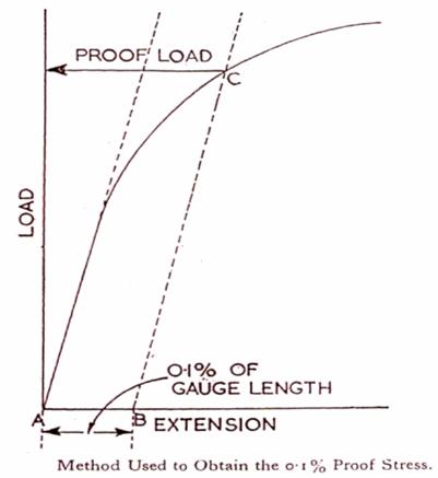
1) TENSILE TEST - The Tensile test of a material is carried out and a stress/strain curve is drawn for the purpose of knowing the elastic limit, proportional limit, yield strength or yield point, tensile or ultimate strength, percent elongation and reduction of area. The first two indicate elasticity, the second and third are strength parameters and the last two indicate ductility.
The material to be tested is machined to standard dimensions and attached to the jaws of tensile testing machine. Before commencing the test, two gauge marks are made on the specimen longitudinally, usually 50 mm or 200 mm apart according to the size of test piece. The test piece is held rigidly at the bottom in the tensile testing machine and the upper end is pulled up by a slowly increasing load.
The amount of elongation in the test piece caused by the load is measured accurately and a load/extension diagram is drawn. The initial straight line part indicate that the extension produced is directly proportional to the load applied. It thus obeys Hooke's Law, which states that, for an elastic body, the strain produced is proportional to the stress applied. Therefore, the values, Stress/Strain = a constant, usually known as Young's Modules of Elasticity (E).
The elastic limit, is defined as the greatest stress that the metal can withstand without experiencing a permanent strain when the load is removed. The elastic limit ae is the elastic load limit pe expressed in Newton divided by the initial cross - sectional area of the specimen, Ao in Sq. m. Thus, ae = Pe/Ao N/m2.
As the load is now increased a point Q is ultimately reached where the curve begins to deviate from the straight line, and if the load is now removed, the specimen will not return to its original length but will be found to have acquired a small permanent plastic extension or "permenent set". Q is therefore called the "Limit of Proportionality". If Pp is the proportional limit load, then proportional limit stress = Pp/ Ao N/ 2
Ao
If
the load is further increased a stage is reached (R), when a sudden
extension takes place with no increase in load. This is known as
Yield Point.
![]() =
Ps/Ao N/m2,
the yield stress is the minimum stress at which the specimen is
deformed (yield) without noticeable increase in load.
=
Ps/Ao N/m2,
the yield stress is the minimum stress at which the specimen is
deformed (yield) without noticeable increase in load.
Beyond
the yield point, the load can be increased again to a certain maximum
value Pu, where a localised reduction of cross-sectional area or
'necking' down occurs. This constriction of area at the neck leads to
a drop in the load, and at the last point of the curve the specimen
is ruptured. The maximum load Pu after which necking down begins is
called the tensile strength load. The tensile or ultimate strength is
the stress corresponding to the maximum load reached before rupturing
the specimen,
![]() =
Pu/Ao N/m2.
=
Pu/Ao N/m2.
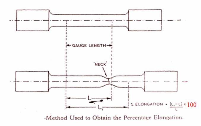
The percentage elongation is the most widely used measure of ductility and is expressed as % elongation = L-Lo \Lo x 100 where Lo is the original gauge length and L is the seperation of gauge length marks after completion of the test and is determined when the broken pieces are fitted together and length measured.
The reduction in area is a second common measure of ductility, but is determined at the necked portion of the fractured specimen and is practically independent of gauge length.
% Reduction in Area =do2-d2 / do2x 100
Where do is the original diameter and & is the diameter at the neck.
The modulus of elasticity at the proportional limit is a measure of stiffness of the material.
E
= Stress/strain =
![]() =
Pp/A°/
=
Pp/A°/
![]() =
Ppi/eAo where e is the
extension at proportional limit. The higher the valve of E, the
stiffer the material.
=
Ppi/eAo where e is the
extension at proportional limit. The higher the valve of E, the
stiffer the material.
Two measure of energy Capacity in common use are modulus of resilience and the modulus of toughness. The ability of a material to absorb energy when deformed elastically and to return it when unloaded is called resilience. This is usually measured by the modulus of resilience, which is the strain energy per unit volume required to stress the material from zero stress to the yield stress.
Modulus
of resilience, Ur=
![]() 2/2E
2/2E
Toughness is indicated by the total area under the stress-strain curve. The moduiur; of toughness is the amount of energy required to cause failure in unit volume of a material and is represented by the total-area under the stress-strain curve.
2) HARDNESS TEST - In Briness hardness test, for iron and steel, a hardened steel ball of 10mm diameter is impressed on a flat polished surface of the sample under a load, usually, 500 or 3000 kg. A load of 750 kg with a 5 mm ball is also used.
The load is maintained for 10 to 15 seconds and the diameter of the impression made on the test piece is subsequently measured by means of a microscope, the order of accuracy being ± 0.01mm.
Brinell Hardness Number, BHN = load on ball/area of indentation
2P
\
![]() D
(D-
D
(D-
![]() D2
- d2) Where,
D2
- d2) Where,
P = Load applied' in Kg.
D = Diameter of ball in mm.
d = Diameter of ball impression in mm.
IMPACT TEST - The Izod Impact test indicates the toughness of a material and its capacity for resisting shock.
The notched bar impact test measures the energy necessary to fracture a standard notched bar by an impulse load and as such is an indication of the notch toughness of a material under shock loading.
The Izod test is carried out by a pendulam type testing machine which employs a cantilevered test specimen 10 by 10 mm in section and 75 mm long having a standard 45° notch 2 mm deep. The notch is made at 28 mm length from one end and the specimen is held in a vise by the length of (75 - 28) = 47 mm such that the notch is just above the vise.
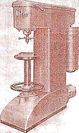
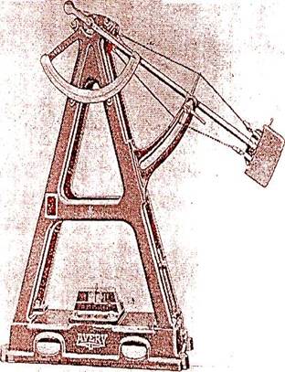
The Brinell Hardness Testing Machine. The Izod Impact Testing Machine.
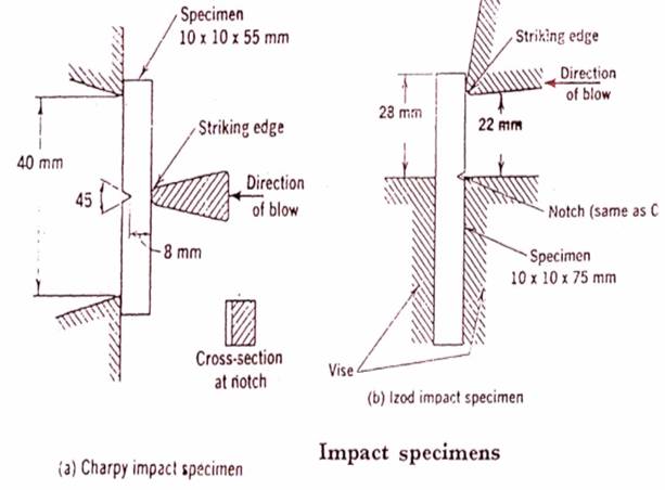
Calculation of energy equation
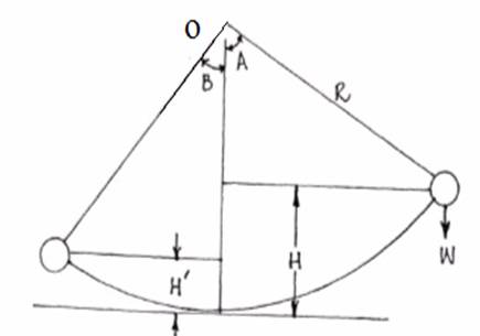
Initial energy = WH = WR (1 - Cos A)
Energy after rupture = WH' = WR (1 - Cos B)
Energy to rupture specimen = W (H - H') = WR (Cos B - Cos A) joules.
Where,
W = weight of pendulam.
H = height of fall of centre of gravity of pendulum.
H' = height of rise of Centre of gravity of pendulum.
A = Angle of fall
B = Angle of rise.
R = distance from Centre of gravity of pendulum to axis of rotation 0.
When the energy required to rupture the specimen is known, the impact strength may be determined. The impact strength is the energy required to fracture the specimen referred to unit cross-sectional area of the specimen at notched cross-section.
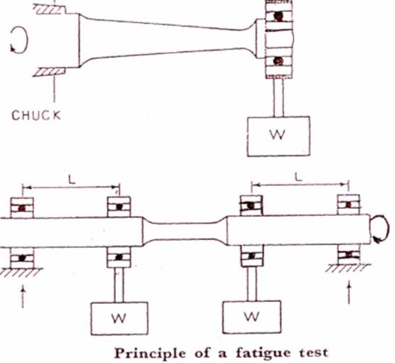
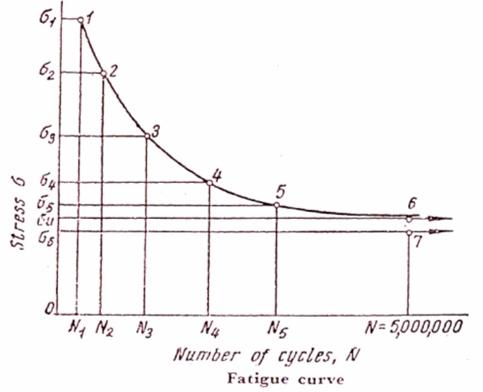
4) ENDURANCE OR FATIGUE TEST - Fatigue test determines the resistance of a material to repeated pulsating or reversing loads.The resistance of a material to fatigue failure is the characteristic of its fatigue limit (endurance limit). The endurance limit is defined as the maximum stress which a specimen can endure without failure "when this stress is repeated for a specified number of cycles.
The fatigue limit is usually determined by subjecting a rotating specimen to completely reversing stresses (tension & compresion) in a symmetrical cycle, called an alternate cycle. A highly polished specimen of circular cross-section is subjected to a bending moment by means of static load. As the specimen is rotated, the outer fibres are subjected to longitudiual stresses that vary from a maximum value in tension to a maximum value in compression and back again to tension during each cycle. A counter records the number of stress cycles that the specimen withstands before it fractures. At least six specimen must be tested to determine the fatigue limit.
The
first specimen is tested at a stress (a MN/m2) equal to
0.6 x ultimate stress for steel and the number of cycles N, at which
failure occurs is determined. The stresses
![]() 1
1
![]() 2
etc. for the
2nd and subsequent specimens are reduced by 20 or 40 MN/m2
depending on the number of cycles which caused the failure of the
first specimen.
2
etc. for the
2nd and subsequent specimens are reduced by 20 or 40 MN/m2
depending on the number of cycles which caused the failure of the
first specimen.
The
results of the tests are plotted on a diagram, Stress (![]() )
vs Number of Cycles (N). The horizontal section is a straight line
and the maximum stress at which failure will not take place after an
infinite number of loading cycles. This value is the fatigue limit.
)
vs Number of Cycles (N). The horizontal section is a straight line
and the maximum stress at which failure will not take place after an
infinite number of loading cycles. This value is the fatigue limit.
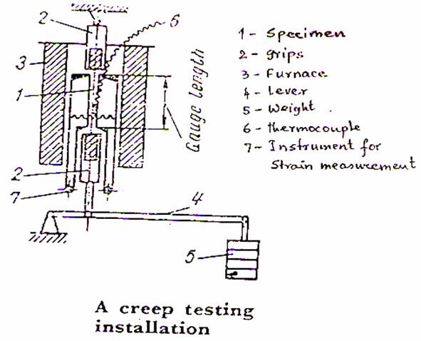
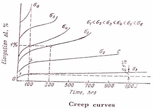
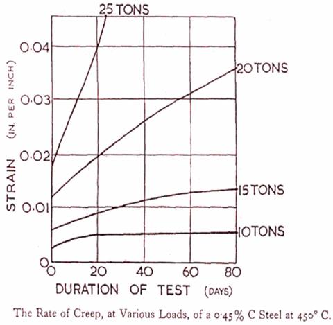
CREEP OR STESS-RUPTURE TEST - Creep is the gradual plastic flow of a material induced by a combination of high temperature and a steady stress below that required to produce a permanent set. The purpose of the creep test is to determine the creep limit, i.e. the maximum stress that may be applied for a long period of time at a given temperature if the rate of creep over this given period of time is not to exceed a specified value.
In a creep testing machine, the specimen is placed inside an electric furnace where it is heated to the given temperature and is constantly subject to a load applied by a lever and weights. The strain in the specimen is measured by an optical extensometer with an accuracy of 0.001 mm. Four or five specimens are tested at each temperature under different loads and elongation vs time curves (creep curves) are plotted for each specimen.
The creep limit may be characterised by the stress which produces a total elongation of 1 percent in 300 hours.
Creep-rupture tests are creep tests which are carried out to the failure of the specimen. In these tests, the time to fracture the specimen, at a given temperature and stress, is measured.
