OPERATION OF INERT GAS SYSTEM :-
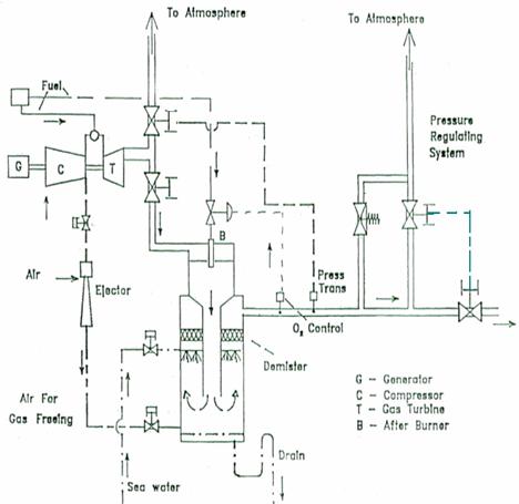
BOILER UPTAKE :- Flue gas is taken from boiler uptake and should bot be too hear the funnel top to avoid entering air with the gas. If rotary gas air heaters are fitted, the flue gas take off point must be before the heaters.
ISOLATING VALVE :- Flue gas is passed through an isolating valve having an open/close indication and soot blower interlock and provided with air sealing arrangement.

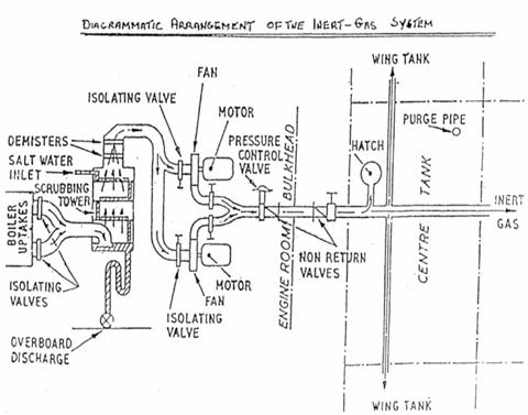
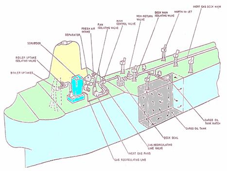
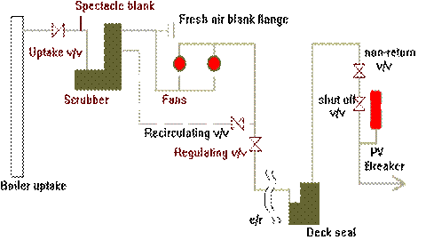
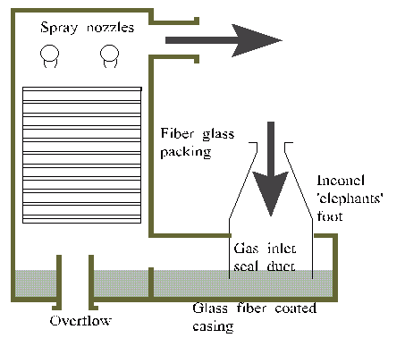
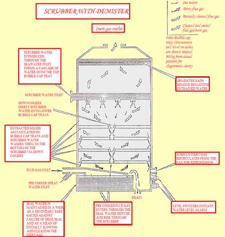
SCRUBBER :- The flue gas then enters the scrubber, whose purpose is to cool the flue gas (to approx 30°C) and to remove sulphur dioxide and parti'culate soot, by sea water spray. Flue gas enters at the bottom of the scrubbing tower and being bubbled through a water seal which cools the gas as well as serves as an jadditional safety device.to prevent any leakage of gas from boiler uptake when the scrubber is opened up for inspection or maintenance. In the scrubbing tower, the gas moves upwards, through water flowing downward. For maximum contact and dwell time between gas and water, there are several layers or trays of packed stones or plastic chippings, perforated impingement plates, venturi nozzles and slots. The internal parts of the scrubber should be constructed of corrosion - resistant materials. A typical example is Ni - cr alloy lined base section, with the upper section protected by a coal tar epoxy paint. Alternatively, the internal parts may be lined with rubber, glass fibre, epoxy resin to protect against high gas temperature and acid corrosion.
The design should be such that under normal conditions of trim and list, the scrubber efficiency will not fall by more than 3%, nor will the temperature rise at the gas outlet exceed the designed gas outlet
temperature by more than 30°C. The location of the scrubber above the load water line should be such that the drainage of the effluent is not impaired when the ship is in the fully loaded condition. Scrubber effluent is acidic (pH between 2 & 4), hence special corrosion resistant pipes are required. Rubber lined steel or stainless steel pipes can be used having a continuous downward slope, for draining.
DEMISTER :-. At the top of the scrubber or in a separate contianer, water droplets in the gas are removed by one or more demisters which may be polypropylene mattresses or cyclone dryers.
BLOWER :- The design requirement is for two blowers, which may be,
One large, one small. Small one used for topping purposes at sea, the large one being capable of meeting maximum requirement.
Two of equal size each being capable of supplying the maximum requirement.
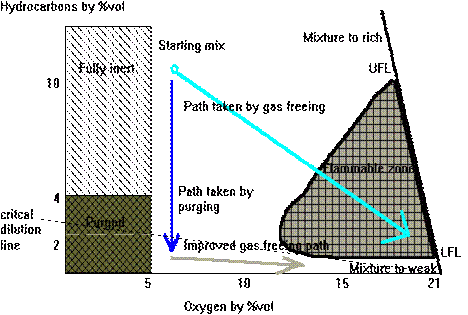
The blowers may also have an air inlet and therefore can be used to gas - free cargo tanks.
Corrosion - resistant materials or coatings must be used in the construction of blowers and casings. Impellers could be Ni-AI-bronze with the casing lined with rubber or fibre glass.
Each blower has an inlet valve and a discharge valve. Casings should be fitted with drains. Sufficient openings must be provided for inspection. Failure of the blowers should be indicated by alarm.
Means should be provided for continuously indicating the temperature and pressure of the inert gas at the discharge side of the blowers.
The blower characteristic should be matched to the maximum system requirement, in the event of discharge of cargo tanks at maximum rate, a minimum pressure of 200 mm water gauge is to be maintained in any cargo tanks after allowing the pressure losses in scrubber, piping, deck water seal etc.
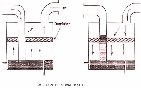
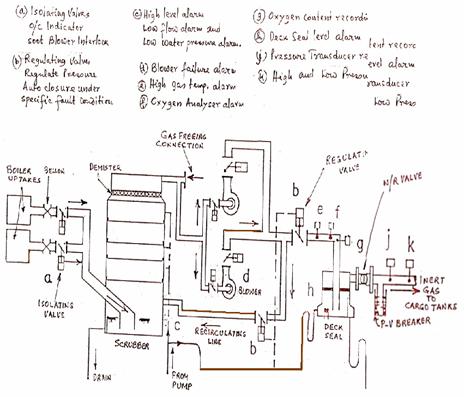
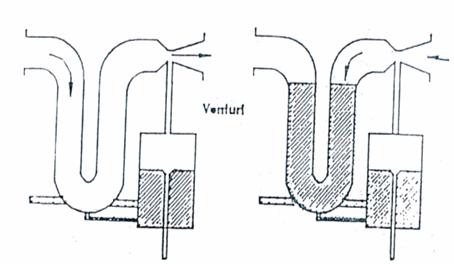
SEMI DRY TYPE DECK WATER SEAL
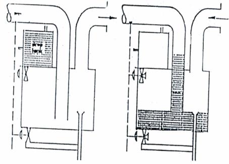
DRY TYPE DECK WATER SEAL
WET TYPE :- Gas is bubbled through the water from the submerged gas inlet pipe but if the tank pressure exceeds, then water is pressed up into the inlet pipe preventing backflow. To reduce carryover of water droplets with the gas sometimes a demister is fitted of wire wool type.
SEMI-DRY TYPE :- Instead of bubbling through the water trap, the inert gas flow draws the sealing water into a separate holding chamber by venturi action thus avoiding water droplets being carried over.
DRY TYPE :- In this type, the water is drained when the inert gas plant in operation (gas flowing to tanks) and filled with water when the inert gas plant is either shut down or the tank pressure exceeds the inert gas blower discharge pressure. Filling and drainage are performed by automatically operated valves controlled by the levels in the water seal and drop tanks and by the operating state of the blowers. The advantage is no carryover of water, drawback is risk of failure of automatically controlled valves which may render water seal ineffective.
An alarm must be activated when the water level falls by a predetermined level, but the seal should not be rendered ineffective when alarm sounds. Heating arrangement or anti - freezing additive (glycol) to be added to prevent freezing of water. Sight glass and inspection cover to be provided to verify water level.
PRESSURE-VACUUM RELIEF BREAKERS :-The cargo tanks must be protected against both pressure and vacuum. Pressure build up to about 1600 -1900 mm (positive) water gauge is relieved by pressure breakers through water and vacuum build up to 400 mm (negative) is also relieved by vacuum breakers.
Protection against large volume of vapour/ air mixtures during cargo loading and ballasting or during discharging is provided typically by high Velocity vents fitted on each cargo tank, in the inert gas main or by masthead risers.
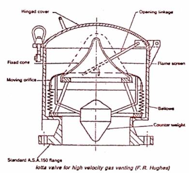
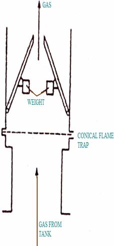
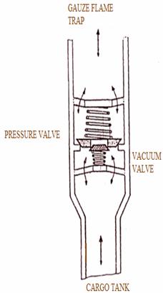
SIMPLE HIGH VELOCITY V\V PRESSURE VACUUM V\V
HIGH VELOCITY VENTS
Tank vapours can be released and sent clear of the decks during loading through large, high velocity vents. The type shown (Figure 6.6) has a moving orifice, held down by a counterweight to seal around the bottom of a fixed cone. Pressure build up in the tank as filling proceeds causes the moving orifice to lift. The small gap between orifice lip and the fixed cone gives high velocity to the emitted vapour. It is directed upwards with an estimated velocity of 30 m/s. Air drawn in by the ejector effect dilutes the plume.
The conical flame screen fixed to the moving orifice to give protection against flame travel will, like the moving parts, require periodic cleaning to remove gummy deposit. The cover is closed (as shown) when the vessel is on passage.
A simpler design of vent (Figure 6.7), has two weighted flaps which are pushed open by pressure build up to achieve a similar nozzle effect. The gauze flame traps and vents tend to collect a sticky residue which should be cleaned off regularly to ensure unimpeded venting.
Tanks should be vented during loading through high velocity or masthead vents. The practice of venting through open tank hatches is dangerous particularly during thundery conditions.
PRESSURE/VACCUM VALVES
Moderate pressures of 0.24 bar (3.5 Ib/in2) acting on the large surfaces in liquid cargo tanks, are sufficient to cause damage and rupture. The pressure on each unit of area multiplied by the total area gives a very large loading on the underside of the top of a tank or other surface. Distortion can result or the metal plate may be ruptured. Similarly, a vacuum within a tank, can result in damage in the form of inward collapse, due to greater atmospheric pressure on the outside. Pressure/vacuum valves (Figure 6.8) attached to tank vents or in the ventilation system, will prevent either over or under pressure. They are set usually so that tank pressure of about 0.14 bar (2 Ib/in2) will lift the larger main valve (the smaller valve will lift with it) and release excess prressure. The vapour passes to atmosphere through a gauze flame trap. A drop in tank pressure compared to that of the outside atmosphere will make the small valve open downwards to admit air and equalize internal pressure with that outside.
Pressure vacuum valves can relieve moderate changes in tank pressure due to variations of temperature and vapour quantity. A drop towards vacuum conditions as the result of the condensation of steam will also be handled by the valve. A rapid pressure rise due to an explosion would not be relieved nor is the pressure/vacuum valve suitable as a vent when loading.