Air compressor :-
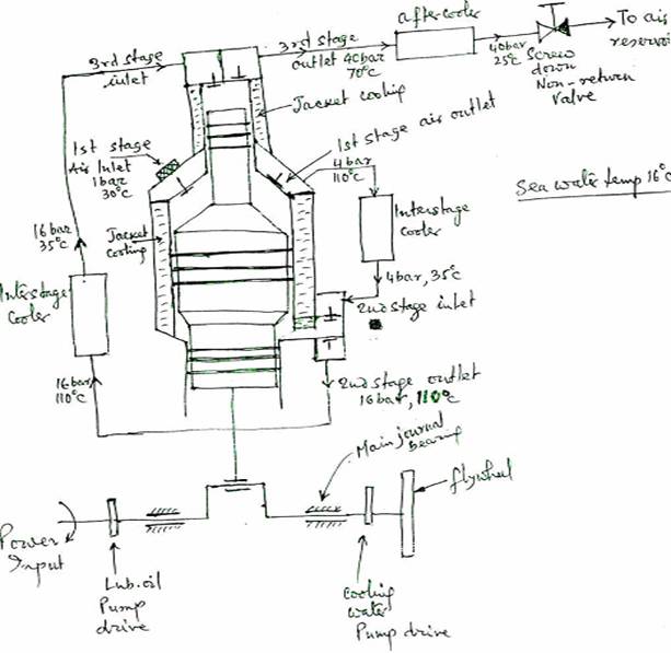
Material:- Crankcase is a rigid casting of closed grain alloy cast iron. Crankshaft is a spheroidal graphite cast iron supported on white metal lined steel backed thin shell bearings. Crankshaft has internal balance weights and carries forged steel connecting rods. Piston is an aluminium alloy with cast iron compression ring and oil control rings. The pistons are connected to the connecting rods by fully floating gudgeon pins running in phosphor bronze bushes. Bearings are lubricated by shaft driven or chain driven gear pumps. The lower cylinder walls are lubricated by oil mist. The air suction & discharge valves are located in pockets in the cylinder heads. The valves are of Hoerbiger type. The moving discs of the valves operate under spring plates and have low inertia to permit rapid action. A combined air filter and silencer is fitted to the compressure air intake. The intercooler is of the single pass type. The shell forms an integral part of the cylinder block casting, the air passing through the tubes. Relief valves are fitted to the air outlet of each stage pressure. To protect the water side against over pressure in the event of cooler tube failure, a spring loaded relief valve is fitted on the cylinder jacket, additionally fusible plugs are fitted. In automatic operation, there are drain valves fitted after each stage which opens at a preset time interval to drain moisture or oil, as well as they are left open during starting & stopping for unloading discharge to suction by pass valve is opened or fitting depressers which hold the suction valve plates on their seats.
Fire in air starting lines :-
(1)Leaky air starting valves in main engine cylinder can cause high temp, combustion gases and dirt to enter in starting air system. Carbon deposits from burning fuel and oily deposits from compressors are available in the air system which may be ignited and produce an explosion in the air start system.
(2)Excessive
lubrication may cause carbon deposits due to dissociation of oil at
high air temp. This carbon can ignite and cause explosion in air
system. Lloyd's require that compressor should be so designed that
the air discharge temp, to the
reservoir should not substantially
exceed 93°C.
Single stage air compressor :-
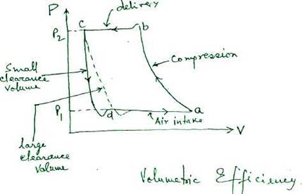
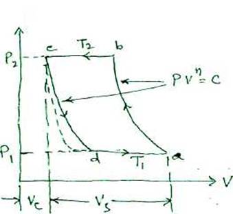
On the compression stroke; the pressure rises to slightly above the discharge pressure. A spring loaded plate type non-return valve opens and the compressed air passes through at approx. constant pressure. At the end of the stroke, the differential pressure across the valve, aided by the valve spring, closes the discharge valve, trapping a small amount of high pressure air in clearance space between the piston and the cylinder head. On the suction stroke, its pressure dropping until such time as a spring loaded suction valve opens and another compression stroke begins.
The heat generated during compression stroke is a waste of energy. This heat of compression adds energy and produces a resultant rise in pressure apart from the press rise due to the action of piston. However, when the air cools, this pressure rise due to the heat generated is lost. The extra pressure due to the heat, is of no use and actually demands greater power for the upward movement of the piston through the compression stroke. Heat can be removed during compression only by isothermal process by cooling cyl.walls, but relatively small surface area and small time available, limits the possibility of heat removal. Multistage compressor with intercooling and aftercooling meet the requirement.
(1) effect of clearance volume :-


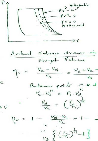
For the same pressure ratio and swept volume, increase in clearance volume, decreases volumetric efficiency."
Too large a clearance volume and the air trapped at the end of compression and deliver}' stroke will expand back to suction conditions before a fresh charge can be drawn in. This can reduce the volumetric efficiency. The clearance volume should be kept as small as safely possible, so that collision between piston and the cyl.cover does not occur in any circumstances.
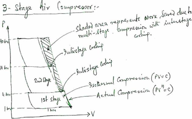
Air Compressor :-Drains :-
Drain valves are fitted after each cooler to drain moisture and oil, intermittently with a preset time interval automatically. Drain valves are also to be kept open during starting and after stopping the compressor.
If 30m3 of free air at relative humidity of 75% at 20°C is compressed to 10 bar every minute, then about 1\2 litre of water would be obtained each minute which should be drained.
Filters :-
Air intake filter is essential for the following reason :-
(i) Air contains suspended abrasive foreign matter which if allowed to enter the compressor, will combine with lub.oil to form an abrasive like sticky paste which increases wear on piston rings liners and valves.
(ii) It can adhere to the valves and prevent them from closing properly which in turn can lead to higher discharge temperature and formation of carbon deposits on valves etc.
(iii) These Carbon-like deposits on valves can become extremely hot at leaky valves and could act as ignition points for air-oil vapour mixtures, leading to possible fires and explosion in compressor as well as in the air delivery lines.
Relieving Devices :-
After each stage of compression a relief valve will normally be fitted set at 10% higher pressure than the normal. Regulations only require the fitting of a relieving device on the h.p stage. Bursting discs must be fitted to the water side of coolers, to relieve pressure in the event of air tube leakage inside the cooler.
Lubrication :-
Choice of lubricant for the cylinder of an air compressor depends on the following factors ■:-
(1)Operating
temperature -
If the operating temp, is high, it reduces oil viscosity which make
easy oil distribution, low film strength, poor sealing and increased
wear. If the temp, is low, oil viscosity would be high, poor
distribution, increased
fluid friction and power loss.
(2)Cylinder Pressure — If the cylinder air pressures are high, then the oil requires to have a high film strength to ensure maintenance of an adequate oil film between the piston rings and the cylinder walls to act as a sealant.
(3) Air condition- As air contains moisture, this can wash out normal mineral lub.oil off the surface and can lead to excessive wear and possible rusting. To prevent this a compounded oil (organic fatty oils ) upto 5 to 25% is to be added along with a rust inhibitor with the mineral oil. This fatty oils can adhere to the metal surface and can act as a good sealant and would not be washed off by moisture content of air.
Compressor Valves :-
Material :-Valve Seat - 0.4% carbon steel hardened and polished working surfaces.
Valve - Nickel Steel, chrome-vanadium steel or stainless steel, hardened and ground, then finally polished to a mirror finish.
Spring - hardened steel duly tempered. Valve leakages causes loss in efficiency and increase in running time.
Effects of leaky Valves :-
(1) First stage suction - Reduced air delivery, increased running time and reduced pressure in suction of the second stage. If the suction valve leaks badly, it may unload the compressor.
(2) First stage delivery - With high pressure discharge air leaking back into the cylinder, there will be less air drawn in, which means reduced delivery capacity and increased discharged temperature.
(3) Second Stage Suction - High pressure and temp, in the second stage suction line, reduced delivery and increased running time.
(4) Second Stage delivery - Increased suction pressure in second stage, reduced air suction and delivery in second stage. Delivery pressure from 1st stage increased.
AIR RESERVOIR:-
Material - Good quality low carbon steel similar to that used for boilers, e.g. 0.2% carbon(max.), 0.35% Silicon (max), 0.1% manganese,0.05% sulphur(max.), 0.05% phosphrous(max.) ultimate tensile strength 460 MN/m2.
Welded construction with class 1 welding regulation if above 35 bar. Welding must be radiographed, annealing must be carried out at about 600°C and a test piece must be provided for bend, impact and tensile test with micrographic and macrographic examination. A safety valve and a fusible plug with melting point at about 150°C. If C02 is used for fire fighting, then the discharge from safely valve and fusible plug to be led to the deck. Stop valve spindle should have arrangement for slow opening to restrict pressure wave in the air pipe line. Pipings to be protected against possible effects of explosion. Drains for the removal of accumulated water and oil are to be fitted to the filters, separators, receivers and lower parts of pipelines.
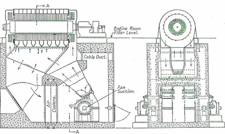
Longitudinal Section thro Alternator Foundation Block. Section thro A.A.
FORCED VENTILATION
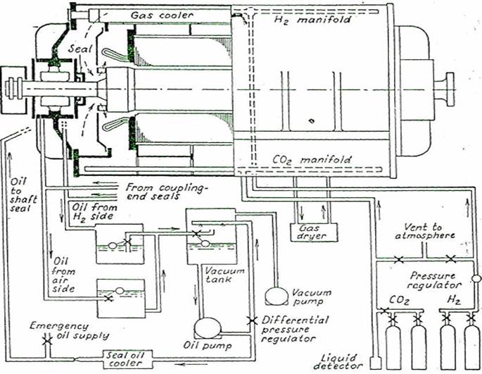
Fig. 336. Arrangement of Hydrogen-cooling System