CONTROL VALVES & THEIR CHARACTERISTICS :
The control valve or correcting element for most control purposes are actuated by diaphragm and spring, with the flow controlled by a specially shaped or characterized valve or plug fitting into a shaped seat.
The assembly is a linear device, i.e. change in pneumatic pressure gives uniform change in valve position. The assembly can be direct acting known as "Air to open" or can be reverse acting known as "Air to close". The choice depends on the system and the consequence of air failure and maintaining a "fail safe" position. The valve plugs are either "Single ported" or "Double ported". In Single ported valve which is normally a globe valve, as the fluid has to change direction twice through the valve, there is a considerable pressure drop across the valve which limits the application of this type of valve. This large pressure drop causes considerable out-of-balance forces when flows are large under high pressure conditions making control difficult and requiring a large diaphragm or high air pressure in the actuator to achieve accurate positioning. They have, however, The advantage of tight shut-off. In general they are suitable for small low flow low pressure drop application. They should be fitted with the inflow on the underside of the valve , otherwise when closing, the large pressure drop caused by the inflow on top of the valve will slam it shut. A double ported valve overcomes the above problem, in which the flow passes across two valves (the lower slightly smaller diameter than the upper to allow fitting) in such a way that the out-of -balance forces are nearly balanced out. The size of the actuator can therefore be smaller but flow resistance is more. It is also more difficult to obtain tight shut-off even if the seats are lapped in, as a change in temperature will cause unequal expansion in valves allowing leakage. 1-2% leakage of the maximum flow rate is normal.
Inherent characteristic - It is the relationship between flow through a control valve and the valve travel or lift. It is the flow which would be obtained by varying the travel from shut to full open, while maintaining a constant pressure drop across the valve.
Installed characteristic - It is the relationship between flow through a valve and the valve travel, when installed in a system which the regulating unit is controlling. The installed characteristic differs from the inherent sometime very considerably and the amount it differs depends on the system "pressure drop ratio".
Pressure drop across the valve - The total pressure differential in system includes the line losses and the drop across the valve. If the line losses are large due to pipe friction and heat exchanger pressure drop etc., then the pressure drop across the valve will be small in comparison. A pressure differential must exist across the valve in order to achieve a flow. If the lines and other fitting would absorb all the available pressure drop, then the valve would be ineffective in controlling the flow.
Pressure drop Ratio = Pressure drop across the valve \ Pressure drop across rest of the system
The three common valve characteristics are :-


1. LINEAR:
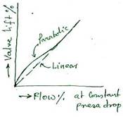
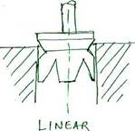
Here the valve produces a flow that gives a straight line graph plotted against lift, i.e. at 40% lift, flow is 40% of max. flow, whilst at 80% lift, flow is 80% of max. flow. These valve plugs have limited applications and would be used when the pressure drop across the valve remains stable and only the load varies i.e. when a large proportion of the system pressure drop is across the valve.
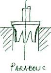
The design may be modified to give parabolic characteristic in which the valve gives a fine control at low flow rates. The design is produced as a contoured plug to deal with dynamic unbalanced forces.
2. EQUAL PERCENTAGE :
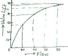
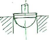
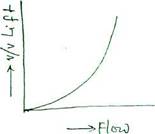
In this system, equal increments of travel give equal percentage changes in the existing flow, thus when the valve plug is near the seat, and the flow is small, then the change in flow is small and when the flow is large , the flow change is large. The increment of lift from 58 to 78 gives an increase in existing flow of 100% i.e. from 20 to 40 . An equal increment of lift from 78 to 98 gives an equal increase in existing flow of 100% i.e. from 40 to 80.
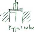
QUICK OPENING - The quick opening valve or poppet valve has a small lift,but it offers the minimum obstruction to flow, with the port area increasing rapidly as the plug leaves the seat. They are used with ON-OFF controllers and may have a slightly shaped plug or a disc valve.
GLAND PACKING FOR PNEUMATIC DIAPHRAGM OPERATED CONTROL VALVE :-
The gland fitted around the valve spindle must effectively seal against leakage of the controlled fluid. The packing used however must not create too high a friction load on the spindle or a load which varies as the spindle moves. The type of packing may be dictated by upper or lower temperature limits; it may be adjustable or spring loaded when fully screwed down. Glands are always long to give good sealing with minimum friction.
TYPES OF GLAND PACKING :-
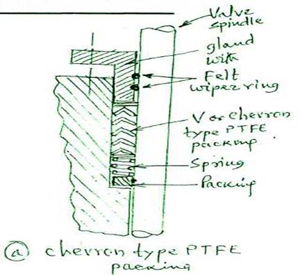
PTFE (Polytetrafluoroethylene) is a plastic material with an inherent ability to minimize friction. It is moulded into V or chevron section which are self adjusting in the stuffing box. No lubrication is necessary but the valve steam must be extremely smooth to ensure a good seal. Gland is tightened down full to give spring tension.
The recommended temperature limits are -40°C to +232°C, and it is resistant to most chemicals.
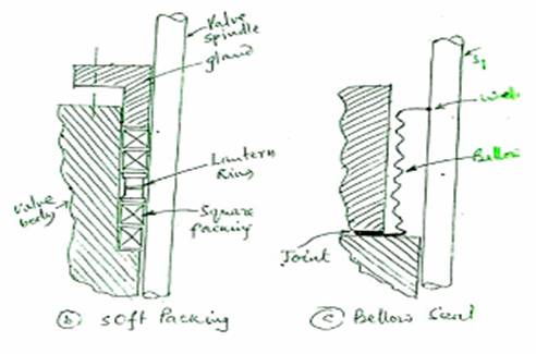
Where asbestos is impregnated with PTFE, a compressible packing is produced with low friction qualities. Rings of square cross-section are used and a lantern ring is fitted in between to enable the entry of lubricant which is normally silicone grease.
The recommended temperature for this material is -73 to +232°C. Silicon grease reduces friction and improves the valve stem action up to temperature of 260°C. It is usually supplied through a screw-operated injector which feeds into the stuffing box; an isolating valve is fitted when the lubricator is used on high pressure valves and is only open when lubrication is taking place.
Graphited asbestos is a formed ring packing made up of asbestos fibre, lead wool, flake graphite, some metal particles, and neoprene as a binder. It is particularly suited to systems containing steam, oil or compressed air. It can be compressed to correct small leakages but must be lubricated to reduce friction and improve sealing. The upper limit of use is 232°C.
(d) Semi-metallic packing rings have an asbestos core which is covered with shredded or covered with shredded or braided aluminium foil. It is used for high temperature and high pressure application , particularly where the valve stem surface is less than perfect. The upper limit of use is 482°C and lubrication should be provided.
(e) Bellows seal with one end welded to the spindle and the other sealed with joint as shown is used where fluid leak could cause a hazard or where fluid cost is very high.