![]()
![]()
BOILER :-
SAFETY VALVES :-
At least two safety valves have to be fitted to any one boiler.
They may be both in the same valve chest, which must be separate from any other valve chest. The chest may be connected to the boiler with only one connecting neck.
The safety valve must never be less than 38mm in diameter and the area of the valves can be calculated from the following formula :-
C x A x P = 9.81 x H x E
Where, H= Total heating surface in m3, E = Evaporative rate in Kg steam per m2 of heating surface per hour, P = Working pressure of safety valves in MN/m2 absolute, A = Aggregate area through the seating of the valves in mm2, C = the discharge coefficient whose value depends upon the type of valve.
C=4.8 for ordinary spring loaded valves, C=7.2 for high lift spring loaded valves, C= 9.6 for improved high lift spring loaded valves, C= 19.2 for full lift safety valves, C= 30 for full bore relay operated safety valves
Typical valve lifts are as follows -
When, C = 4.8 , lift = Di \24 approximately
C = 7.2 and 9.6, lift = D2\12 approximately
C= 19.2 and 30, lift = D3\4 "
Where D1>D2 >D3 and Di,D2 and D3 are the diameters of the seating of the valves in mm.
The fully cellular container ship is equipped to carry containers in the holds and on the weather deck by means of special structural arrangements and devices. Within the holds of such vessels, ther is a cellular structure of angle bars forming container guides into which the containers are stowed, one on top of another.
Differences in the ordinary and high lift designs
|
Ordinary |
High Lift |
Improved high lift |
|
Winged valve |
Winged valve |
Wingless valve |
|
No waste piston |
Waste piston |
Waste piston |
|
|
No floating ring |
Floating ring |
Improved High Lift
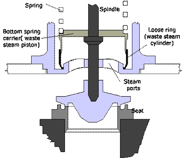
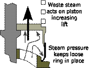
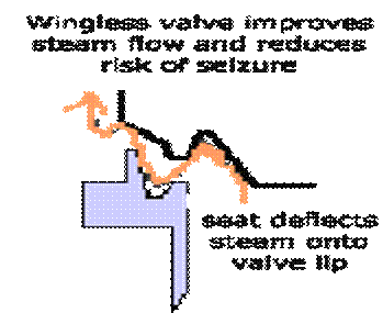
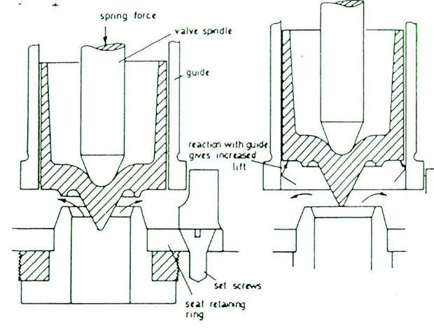
A special shaped valve seat and a lip on the valve without valve wings improves waste steam flow and increases valve lift against the increasing downward force of the spring and reduces risk of seizure. Bottom spring cover serves as waste steam piston and a floating ring serves as a cylinder gives increased valve lift and seizure risk is reduced.
For superheated steam the aggregate area through the seating of the valve is increased, the formula is :-
As = A(l+Ts/555)
Where, As = Aggregate area through the seating of the valves in mm2 for saturated steam.
A =aggregate area through the seating of the valves in mm2 for saturated steam.
Ts= degree of superheat in °C.
As specific volume increases with rise in temp, As would be higher than A with the rise in degree of superheat and more escape area is required to avoid accumulation of pressure.
The area of the valve chest connecting neck to the boiler must be at least equal in cross sectional area to one .half of the aggregate area A. The waste steam pipe and steam passage from the valves must have cross sectional area of at least :-
1.1 x A for ordinary, High Lift and Improved High Lift safety valves.
2 x A for full lift safety valves.
3 x A for full bore relay operated safety valve.
There must be an open drain pipe fitted to the lowest part of the safety valve chest on the discharge side of the valves and this pipe should be led clear of the boiler and must have no valve or cock fitted throughout its length. This drain pipe must always be kept clear for if it gets choked, there is a possibility of overloading the valves due to hydraulic head or damage resulting due to water hammer.
Full Lift Safety Valve (for pressures upto 63 bars) :-
This type of valve does not incorporate a waste steam piston, instead the valve itself operating inside the guide acts as a piston in a cylinder. When the valve lifts during operation at the blow-off pressure by a small amount, the escaping steam pressure can then act upon the full area of the valve, this increase the lift until the lower edge of the valve just enters the guide. At this point the reaction pressure generated by the escaping steam with the guide causes the valve to lift further until it is fully open. When the valve is fully open, the escape area is said to be equal to the area of supply through the seating.
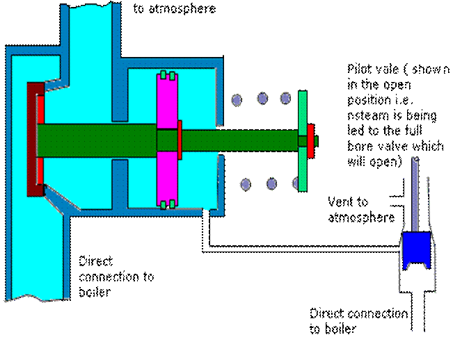
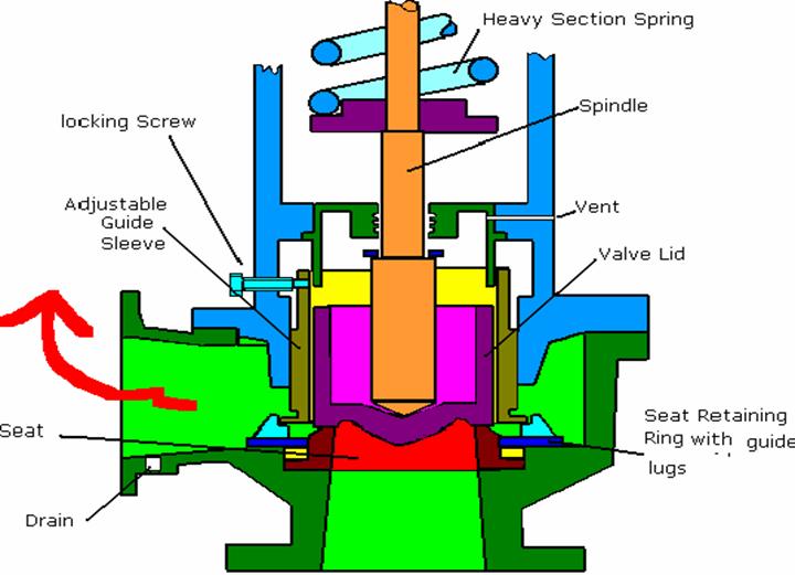
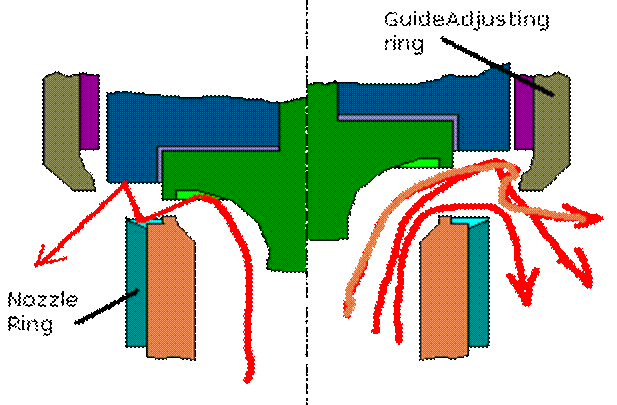
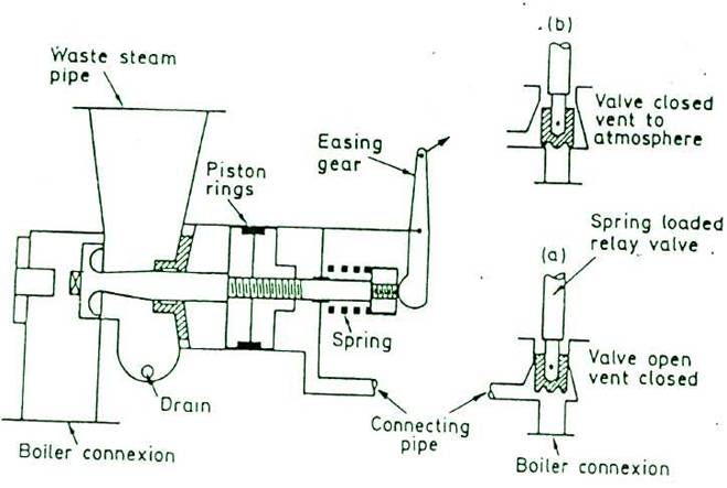
Full Bore Safety Valve :- The full bore relay operated safety valve is suitable for high pressure boilers whose working pressure is in excess of 21 bar(2.1 MN/m2). When the boiler pressure reaches the desired blow off pressure, the relay valve lifts first, admitting the boiler steam pressure into the cylinder of the main valve while blanking the atmospheric vent. Since the area of piston of main valve cylinder is about twice that of the relay valve, the main safety valve opens against boiler pressure. When the boiler pressure falls, the relay valve closes first, uncovering the vent to atmosphere which communicates the cylinder of main valve with the atmosphere and the boiler pressure then causes the main valve to close rapidly. Higher the boiler pressure, the more rapid will the valve close and hence greater saving in steam. The main valve spring assist closing of the valve and ensures the valve to remain closed when the boiler is cold. If the safety valve is to be used for superheated steam, the relay valve connection is generally taken from saturated steam drum, so that relay valve and main valve piston and cylinder are subjected to lower temperature operation.
MATERIAL: - Materials used for valve, valve spindle, valve seats compression screws and bushes must be non-corrosive metal such as stainless steel or monel metal. Valve chest is normally made of cast steel.
Maintenance and Adjustments :- All working parts of safety valve must be sound, in alignment and able to function correctly. Lip clearance, seating width, wing clearance etc must be as per boiler makers specification. When dismantled, all metal parts are hung by cords and sounded by gently tapping with a hammer and parts sound heard for abnormality like hair cracks. Drains to be checked and easing gear tried.
Adjustment of safety valve :- With the compression rings removed, to screw down compression screw and the boiler pressure raised to the required blow-off pressure. To screw back compression screw until valve blows, then screw down the compression screw carefully tapping the valve screw downwards very lightly whilst doing so, until the valve returns to its seat and remains closed. When set, split compression rings are to be fitted along with hood, key, pad locks and easing gear. Finally easing gear to try out to ensure the safety valve is in working order.
Accumulation of Pressure Test - According to classification society requirement, boiler safety valve when initially fitted must be subjected to an accumulation of pressure test to ensure the valves are of correct discharge capacity for the boiler. To conduct such a test, all feed inlets and steam outlets are shut and maximum firing rate arranged. Accumulation of pressure must then not exceed 10% of the working pressure. Duration of test(water permitting ) is not to exceed 15 minutes for cylindrical boilers and 7 minutes for water tube boilers. In water tube boilers the test may be waived if damage to superheaters or economizers could result from the test.
OPENING UP A BOILER ;-
(i) It is advisable, if time is available, to allow the boiler to cool down in its own time after shut down and then to pump out the water. Sudden shock cooling due to complete blow down under pressure can be avoided.
(ii) Ship side blow down valve must be opened first and then the blow down valve on the boiler can be gradually opened. Blow down valve must be closed, when the pressure is low enough, to avoid entry of cold sea water.
(iii) To allow for the boiler to cool down and lose all its pressure and when the pressure is atmospheric, air cocks and gauge glass drains are opened.
(iv) Preferably the top boiler door is opened first by holding the door with a rope, slackening the dog retaining nuts slightly and tapping the door with a wooden plank standing at a distance. After knocking the door open, then the dog nuts can be open fully and the door removed from place and taken out.
(v) After checking the water level near the bottom door, and if drained, the bottom door can be knocked similarly and taken out. Both the top and bottom doors are not opened at a time to avoid circulation of cold air and thermal shock.
(vi) When it is confirmed that inside temperatures of furnace and water drums have come close to ambient temperature, then entry inside can be made for inspection.
DEFECTS, CAUSES AND REPAIRS FOR AUXILIARY BOILERS :-
(1) FURNACE :
Defects that could occur to a furnace are : deformation, wastage and cracking .
Deformation - With cylindrical furnaces, this can be determined by sighting along the furnace or by gauging. Causes of deformation are scale, oil, sludge or poor circulation resulting in overheating of the furnace and subsequent distortion. Local deformation could be repaired by cutting through the bulge, heating and pressing back the material into the original shape and then welding. Alternatively, the defective portion could be cut out completely and a patch welded in its place. If the furnace is badly distorted then the only repair possible may be renewal. A weakened furnace may be repaired temporarily by pressing back the deformation and welding plate stiffners circumferentially around the furnace on the water side.
Wastage - The causes of wastage are corrosion and erosion. Localized corrosion could be dealt with by cutting out the defective portion of furnace and welding in a new piece of material. If the wastage takes place to a great extent, then renewal may be the only solution.
Cracks — Cracks are caused by mechanical straining or due to overheating, and the defect is generally termed as grooving. If the grooving is shallow compared to plate thickness, depth can be ascertained by drilling or by ultrasonic detection. To repair, it is usual to cut out the groove and weld. However, if the grooving is deep, the material is cut right through and welded from both sides.
(2) COMBUSTION CHAMBERS :- Defects in combustion chamber are due to deformation, wastage, cracks and water shortage.
Deformation - Generally the combustion chamber top would be the first place to suffer distortion due to overheating and subsequent water shortage. Sometimes plate bulging could be due to corrosion of stays or tubes leading to a reduction in the support for the plating. Remedy would be renewal of stays or tubes. Local deformation can be repaired by cutting out the defective portion of the plate, generally through the line of stays or tubes and welding a new piece of plate. This avoids a continuous weld and reduces the risk of defects that could occur due to contraction stresses. Badly distorted combustion chamber plating is best renewed.
Wastage - Leakages past tubes, stays and through riveted seams could cause wastage. If the wastage is not extensive then the defective portion of plate can be built up by welding and the tubes or stays renewed where required. For extensive wastage, defective portion of the plating should be cutout and a new portion welded in.
Cracks - Cracks can develop due to overheating and mechanical straining. Likely places are, the landing edges of combustion chamber seams on the fire side due to doubling of plate thickness and impairing of heat transfer and around tubes and stays due to straining of the boiler and or scale build up around the necks of the tubes or stays. Cracks or radial grooving are repaired by cutting out the crack and filling in with welding. If the grooving is extensive, the defective portion of plate should be cut out and a new portion welded.
(3) SHELL AND END PLATES :- Defects are wastage and cracking.
Wastage - Generally occurs at places of leakages such as riveted seams and boiler mountings. Leakages at seams and between boiler mountings and shell in the water region of the boiler lead to salt deposition due to water flushing off to steam, leaving behind some of the salts it contained. These salts can cause wastage of material. Repairs for wastage may be built up by welding or by renewal of the defective portion of plate, if the wastage tends to be excessive. Seam leakage if slight, is repaired by re-caulking of the seam.
Cracking - Cracking is caused by the caustic embrittlement i.e. concentration of caustic soda (NaOH) under stress. In addition caustic embrittlement can cause grooving or flanged end plating. Repairs for grooving is done by welding. Repairs for cracks due to embrittlement generally necessitate renewal of the affected portion of plate.
CAUSES OF BOILER CORROSION AND EFFECTS OF SALTS AND GASES :-
(1) Electro chemical corrosion - When the boiler water is acidic in nature(pH value less than 7) then hydrogen ions in contact with the metal surface become hydrogen atoms by taking an electron from the metal. The resultant metal ion(caused through loss of electrons) combines with the hydroxyl ions in a metallic hydroxide, hence the metal is corroded. Hydrogen atom may form a polarizing layer upon the metal surface and prevent further corrosion. If however, dissolved oxygen is present in the water, it will combine with the hydrogen to form water and no polarization will occur and corrosion will continue. Also, if the water is acidic enough, the hydrogen can leave the surface of the metal in the form of hydrogen gas, again preventing polarisation and continuing corrosion. Hence, the need for the boiler water to be alkaline and with little or no dissolved oxygen content.
(2) Oils - If lubricating oil contaminates the feed system, then animal and vegetable oils can decompose in the boiler and liberate their fatty acids which can cause corrosion. Also oil can adhere on the heating surfaces causing overheating due to inspaired heat transfer. Oil can also cause priming due to excessive ebullition.
(3)Mechanical Straining - Mechanical straining of boiler parts could be due to mal-operation of the boiler, raising steam too rapidly from cold, poorly connected internal feed pipes, fluctuating feed temperature and steaming conditions. Grooving is caused due to mechanical straining and corrosion can result at the grooving. Pitting corrosion can also occur due to differential aeration.
(4)Galvanic Corrosion - When two dissimilar metals are present in a saline solution, galvanic action takes place, resulting in the corrosion of more base metal. Sacrificial zinc anodes are frequently used to give cathodic protection to steel plating scotch boilers.
(5)Caustic
Embrittlement -
Caustic embrittlement or intercrystalline fracture is caused by high
concentration of caustic soda(sodium hydroxide NaOH) and the material
under stress. Concentration of NaOH required for embrittlement to
occur vary with operating
conditions, roughly about 6000
grains/gallon at 300°C is a guide to the amount of concentration
required, NaOH depresses
the solubility of sodium sulphate which can precipitate and form a
protection for the material. It is recommended that the ratio of
sodium sulphate to caustic soda should not fall below 2.5 at all
times. Other substances that have been used as inhibitors against
caustic embrittlement are quebracho tannin and sodium nitrate.
Caustic corrosion in high pressure boilers is usually indicated by
gouging of the tubes and is caused by excess sodium hydroxide and a
concentrating mechanism.
(6)Salt Water - Average sea water contains 32,000 ppm of total dissolved solids.
Salt - Sodium Chloride Magnesium chloride Magnesium sulphate Calcium sulphate Calcium Bicarbonate
|
Chemical symbol |
% of total |
ppm |
|
|
Dissolved solids |
|
|
Nacl |
79 |
25,000 |
|
Mgck |
10 |
3,000 |
|
MgSO4 |
6 |
2,000 |
|
CaSO4 |
4 |
1,200 |
|
Ca(HCO3) 2 |
Less than 1 |
200 |
Sodium chloride (Nacl) :- Heavy concentration of Nacl can cause foaming and priming. With varying conditions of boiler water pressure and temperature, solubility of salts vary, as also with the presence of other salts and compounds. Under normal condition, solubility of Nacl is quite high and they remain in solution, but under high temperature and pressure, salts may come out of solution. Nacl could in conjunction with magnesium sulphate form sodium sulphate aud magnesium chloride. Sodium sulphate can precipitate and form a protection for the material against caustic embrittlement.
2Nacl + MgSO4 -> Mgcl2 + Na2SO4
Magnesium chloride(Mgcl2) :- Mgcl2 is soluble under normal boiler conditions, but it can to some extent be broken down forming hydrochloric acid and magnesium hydroxide.
Mgcl2 + 2H2O -> Mg(OH)2 + 2Hcl.
Mg(OH) 2 has a low solubility and can deposit as a scale but with suitable treatment it can be precipitated in the form a non-adherent sludge which can be blown out of the boiler. Hydrochloric acid can cause corrosion with the formation of ferrous chloride which further breaks down to form an iron hydroxide with regeneration of hydrochloric acid and corrosive cycle can continue. With suitable treatment this corrosion can be prevented.
2Hcl + Fe -> Fecl2 + H2
Fecl2 + 2H2O -» Fe(OH) 2 + 2Hcl,
Magnesium Sulphate(MgSO4) ;- It is soluble under normal boiler conditions, but if too high a density is carried it may deposit and form scale. This scale could to some extent combine with Nacl, forming magnesium chloride and sodium sulphate.
Calcium Sulphate(CaSO4) :- This salt can deposit and form a hard tenacious scale which greatly affects the rate of heat transfer, overheating and failure of heating surface. When a steam bubble is formed upon a heating surface, the plate, under the bubble, becomes overheated., as it is insulated momentarily from the water. The water, containing salts in solution, in contact with the plate around the periphery of the bubble also becomes overheated. Salts whose solubility decreases with rise in temperature (like CaSO4), will deposit in the form of a crystal ring, because the water has become supersaturated locally with these salts. Further, when the bubble bursts, the water coming in contact with over heated plate will again gets overheated locally, causing more salt deposition. Thus salts whose solubility decreases with increase in temperature, will form scale on heating surfaces and sludge upon cooling surfaces. Whereas salts whose solubility increases with increase in temperature do not normally form scale upon heating surfaces but a sludge may be formed if their saturation point is reached.
Calcium Bicarbonate:- This salt is decomposed when heated, liberating carbon dioxide and Calcium Carbonate precipitation.
Ca(HCO3) -> CaCO3 + CO2 + H2O.
CaCOs has a low solubility and it decreases with increase in temperature and therefore forms scale. Scale is soft and porons in nature and is not such a poor conductor of heat as Calcium sulphate scale.
Hardness Salts :- Alkaline hardness salts are hydroxides, carbonates and bicarbonates of Calcium and Magnesium. The bicarbonates of Calcium & Magnesium are called temporary hardness salts as they decompose by heating or boiling of water, liberating carbondioxide and leaving carbonate. Non-alkaline or permanent hardness salts are the chlorides, sulphates, nitrates and silicates of calcium and magnesium and hardness due to these salts is not removed by boiling or heating the water. Only chemical treatment can remove this hardness.
Silicates - Silica present in water in low pressure boilers, combines with calcium and magnesium to form hard scales of calcium & magnesium silicates. In high pressure boilers silica may combine with other elements to fonn complex silica scales which are glassy, extremely hard and difficult to remove. If silica content in the boiler is in excess 20ppm (amount decreases as boiler pressure increases), it is likely that it will volatilize and deposits on turbine blades.
Carbondioxide - Carbon dioxide may be absorbed by boiler feed water due to contact with atmosphere and also due to breakdown of bicarbonate and carbonates present in the feed. If the water contains dissolved carbon dioxide, carbonic acid may be formed which can cause corrosion. Carbonic acid partially dissociates into hydrogen ions and carbonate ions, hence hydrogen ion concentration of the water increases.
CO2 + H2O -> H2CO3 H2CO3 ^H+->(HCO3)
The bicarbonate ions combine with ferrous metal to form ferrous bicarbonate, which dissociates into ferrous carbonate and carbonic acid, which is redissolved into the water.
Fe + (HCO3) -» Fe(HCO3) Fe(HCO3) ~> FeCO3 +H2CO3 Fe + H2CO3 -> FeCO3 + H2
If there is supply of dissolved oxygen in the water, the ferrous carbonate is converted into ferric hydroxide with regeneration of carbondioxide.
4FeCO3 + O2 + 6H2O -> Fe(OH) 3 + 4CO2
Ferric hydroxide may break down further to form ferric oxide with loss of water .
4Fe(OH)3 -» 2Fe2O3 + 6H2O
Hydrogen —Hydrogen ions formed during reaction in feed water, can penetrate the boiler tube metal and react with carbon,(C + 4H -> CH4) to produce methane. This carbon loss weakens the metal and the methane gas exerts a pressure which separates the grains of steel. When hydrogen is released by caustic corrosion, hydrogen damage can also occur.
BOILER WATER TREATMENT :-
The objectives of feed water treatment are as under -
1.
Prevention of
scale formation in the boiler, feed system, condensate system and in
the
machinery where the steam is being utilized by
(a)using distilled water or
(b)precipitating all scale forming salts into the form of a non-adherent sludge.
2. Prevention of corrosion by maintaining the boiler water in an alkaline condition and free from dissolved gases.
3. Control of sludge formation and prevention of carry over with the steam.
4. Prevention of foreign matter from entry into the boiler, such as oil, waste. Mill-scale, iron oxide, copper particles, sand, weld spatter etc., by careful use of oil heating arrangement, effective pre-commission cleaning and maintaining the steam and condensate system in a non-corrosive condition.
5. Prevention of damage to machinery due to impure steam being generated.
6. Prevention of outage time due to failure of the boiler or its associated equipment.
7. Reduction of time for repair or maintenance.
BOILER
WATER TREATMENT CHEMICALS :-
According to
the operating pressure and type of boiler, different
chemicals are added as per the recommendation of boiler suppliers and chemical manufacturers.
(1) Lime and Soda Treatmentf Low Pressure boilers)
Lime,Ca(OH)2 (Calcium hydroxide) and Soda ash, (Sodium carbonate.NaiCOs) are used to deal with the calcium and magnesium compounds in the boiler water. Lime reacts with temporary hardness salts and magnesium compounds as follows :-
Ca(HCO3) 2 + Ca(OH) 2 -» 2CaCO3 + 2H2O Calcium bicarbonate-
Mg(HCO3) + Ca(OH)2 -> Mg(OH)2 + 2CaCO3 + 2H2O Magnesium bicarbonate
MgSO4 + Ca(OH)2 -> Mg(OH) 2 + CaSO4 Magnesium sulphate
Mg(NO3) 2 + Ca(OH)2->Mg(OH)2 + Ca(NO3)2 Magnesium nitrate
Mgcl2 + Ca(OH)2 -> Mg(OH)2 + Cacl2 Magnesium chloride
Sodium Carbonate(soda ash Na2CO3) reacts with the Calcium Compounds originally in the water and those obtained through Ca(OH)2 treatment.
CaSO4 + Na2CO3 -> CaCO3 + Na2SO4 Calcium sulphate
Cacl2 + Na2CO3 ->CaCO3 + 2Nacl Calcium chloride
Ca(NO3) 2 + Na2CO3 -> CaCO3 + 2Na(N0) 3 Calcium nitrate
The combination of lime and soda gives zero hardness and alkaline feed water. The precipitated sludge are removed by blow down. • Unevaporated fresh water used as make up feed contains alkaline hardness salts and should be treated with soda and lime before entry into the system.
(2) Caustic soda treatment Sodium Hydroxide, NaOH reacts with the alkaline and non-alkaline magnesium compounds and it also forms sodium carbonate which can react with the non- alkaline calcium compounds.
Ca(HCO3) + 2NaOH -> CaCO3+ Na2CO3+ 2H2O Mg(HCO3) 2 + 4NaOH -> Mg(OH) 2 + 2Na2CO3 + 2H2O Mgcl2 + 2NaOH -> Mg(OH)2 + 2Nacl MgSO4 + 2NaOH -> Mg(OH) 2 + Na2SO4 Mg(NO3)2 + 2NaOH -> Mg(OH)2 + 2NaNO3
Sodium Carbonate which is formed by employing sodium hydroxide should be in sufficient quantity to deal effectively with the non-alkaline Calcium Compounds. If falls short, Sodium Carbonate will have to be used in conjuction with sodium hydroxide. The chemical reserves give the required alkaline environment to prevent corrosion and protect against the ingress of hardness salts. In order to prevent salts being precipitated in the feed system the chemicals are preferably added directly to the boiler. The precipitated salts are removed by blowdown.
(3) Congruent phosphate - Since at high temperature, sodium carbonate can breakdown to form sodium hydroxide (Na2CO3 + H2O -> 2NaOH +CO2) , high concentration of caustic soda formed beneath deposits can cause serious and rapid corrosion of boiler steels. For this reason congruent or co-ordinated phosphates are added. The pH and phosphate levels are controlled by dosing a mixture of di- and tri- sodium phosphate to bring down the level of caustic soda. However very sophisticated control is necessary with very narrow limits for both pH and phosphate. The alkalinity buffer against acid chloride attack is reduced, and if it is not possible to maintain low chloride level, combined caustic soda/phosphate treatment is advisable. For the precipitation of scale forming salts into a sludge and to give alkalinity, phosphates ■ are used. Phosphates will combine with calcium and magnesium compounds to form their phosphates.
3CaCO3 + 2Na3PO4 -> Ca3(PO4)2 + Na2CO3 3CaSO4 + 2Na3PO4 -> Ca3(PO4)2 + 3Na2SO4 3Cacl2 + 2Na3PO4 -> Ca3(PO4)2 + 6Nacl MgSCU + 2Na3PO4 ->Mg(PO4)2 + 3Na2SO4
(4) Coagulants - Specific water soluble polymens are used for coagulation,
dispersion and to condition the precipitates into the form of non-adherent sludge which can be easily blown out of the boiler. Synthetic organic polymers of high molecular weight e.g. sodium polycrylate prevents scale deposition and minimizes sludge formation. It may also loosen any scale already present in boiler. Sodium aluminate can also be used with the lime and soda treatment, it can break down and form aluminium hydroxide which combines with the magnesium hydroxide in a flocculent form. Starch, tannin, gels and casein etc. are also used as coagulants.
(5) Oxygen Scavengers - Oxygen scavenging chemicals used for deaerating the water are sodium sulphite or hydrazine.
2Na2SO3 + O2 -> 2Na2SO4
The use of sodium sulphite is restricted to boilers operating at pressures upto 40 bars. At high pressure boilers, the sulphite can break down to give hydrogen sulphide(H2S) and sulpher dioxide which can attack steel, brass and copper. Moreover , sodium sulphite reaction rate with oxygen is maximum at about 7 pH, hence the sodium sulphite should be injected into the system before any alkaline ingredients are added. Sodium sulphite also increases dissolved solids content.
Hydrazine solution (60% Hydrazine & 40% water) can be used for oxygen scavenging in high pressure boilers.
N2H4 + O2 -> 2H2O + N2 Hydrazine —> Ammonia + Nitrogen
As hydrazine reaction also forms water, it does not increase the boiler density. Excess hydrazine may decompose into ammonia which could lead to steam and condensate line corrosion. However, a controlled excess is beneficial to the steam and condensate as it counteracts the effect of carbon dioxide corrosion. Hydrazine should be stored in a cool well ventilated place since
it is toxic and a fire hazard. When handling, protective clothing should be worn as like caustic soda. Hydrazine should be injected into de-aerated feed.
(6) Condesate line treatment - where the steam is wet and also in the condensate system, corrosion can occur due to the presence of carbon dioxide carried over with the steam. To protect against corrosion and to ensure alkalinity, cyclohexylamines are added.
Two distinct classes of amines are added :-
Filming amines - Octadecylamine is added which is insoluble in water at room temp, but volatile in steam. It protects against corrosion by forming a molecular water-repellent protective film on metal surface.
Neutralising amines — Common amines used are cyclohexylamine and morpholine, which are colourless, steam-volatile and used to neutralise carbon dioxide in steam, condensate and feed system.
(7) Antifoams - These are complex organic compounds of high molecular mass and are effective at reducing carryover due to foaming and thus improving steam purity. For safety reasons, it is recommended that they are only used as an additional safeguard and are not used to allow total solids to rise higher than would be allowed without their application.
(8) Prevention of Caustic embrittlement - Sodium sulphate is used for the prevention of Caustic embrittlement (due to caustic soda treatment) by giving a coating and the ratio of sodium sulphate to caustic soda to be kept at or above 2.5. Alternatively sodium nitrate may be used and the ratio of sodium nitrate to caustic soda not to fall below 0.4 to 1 at all times.
BOILER OUT OF SERVICE :-
For short period out of service (e.g. 2 or 3 days), boiler should be filled up with alkaline feed water and fire intermittently to keep the boiler pressure above about 3.5 bar. Alternatively, the boiler could be filled up while hot, with hot deaerated alkaline feed water and about 0.5 kg of anhydrous sodium sulphite added for each tonne of water in the boiler. The boiler must be topped up periodically and any air in the system must be got rid of. With fire tube boiler out of service for short periods, boiler to be filled up with alkaline feed water at the recommended value. For long period out of service, boiler should be drained completely and dried up by means of heater units. Then trays of quicklime should be placed internally in suitable positions throughout the boiler before it is sealed up. Blanks should be fitted in the pipe connections and at the blow down line. The lime should be renewed at least once in two months.
CLEANING OF NEW BOILERS :- Pre-commissioning chemical cleaning of new boiler is required to remove surface rust, mill scale, dirt and traces of oil which occur during boiler manufacture and erection. Procedure is :-
(1)To
Boil out the boiler at atm.pressure with an alkaline solution to
remove traces
of oil and dirt.
(2)To wash out boiler with a heated acid solution to remove rust and mill scale.
(3)To Rinse boiler with a weak acid solution.
(4)To flush the boiler out repeatedly to remove debris.
(5)To passivate the boiler by using hydrazine.
WATER TREATMENT RECOMMENDATION (BS1170 OF 1983)
|
PURPOSE |
CHEMICAL |
TYPE OF BOILER |
|
|
1. |
To prevent scale |
Sodium Phosphates |
All boilers upto 84 bar W.P. |
|
2. |
To give alkalinity and minimize corrosion. |
Sodium Hydroxide or Sodium Carbonate. |
All upto 84 bar W.P. All upto 60 bar W.P. |
|
3. |
To condition sludge |
Po lyelectro lytes or Starch or Tannins or Sodium aluminate |
All upto 84 bar W.P. All upto 84 bar W.P. All upto 84 bar W.P. All upto 31.5 bar W.P. |
|
4. |
To remove traces of Oxygen. |
Sodium Sulphite or Hydrazine. |
All upto 42 bar W.P. From 31.5 to 84 bar W.P. |
|
5. |
To reduce risk of Caustic Cracking |
Sodium Sulphate or Sodium Nitrate |
All upto 31.5 bar W.P. All upto 31.5 bar W.P. |
|
6. |
To reduce risk of carryover of foam. |
Antifoam |
All upto 84 bar W.P. |
|
7. |
To protect feed and condensate systems from corrosion. |
Filming Amines, Octadecylamine. or Neutralising Amines Cyclohexylamine & Morpholine. |
All upto 60 bar. From 17.5 to 84 bar. |
BOILER WATER TESTS :- The representative sample of boiler water where collected, if above 60°C , it is necessary to fit a cooler, for both protection of the operator from scalding and to prevent a proportion of the sample flashing off as steam, which would give falsely high readings. Where boiler water sampling is fitted with an internal collection pipe, it should be checked that the pipe is remote from the feed discharge, otherwise contamination of the sample with feed water will give falsely low test readings.
(1) ALKALINITY TEST
(a) Alkalinity to Phenolphthalein
100 ml sample of boiler water taken. 1 ml (10 drops) of phenolphthalein added.
As phenolphthalein is less alkaline to hydroxides and carbonates, the water sample will turn pink if those are present.
N/50 sulphuric acid is added to clear the sample.
Calculation : ml. of N/50 acid used x 10 = ppm of CaCO3.
The acid used after colouration will first neutralize the hydroxides, forming salts, it will then react with carbonate molecules present to form bicarbonate molecules. Bicarbonate molecules are less alkaline than phenolphthalein, hence the pink colouration will disappear once all the hydroxides and carbonates have been dealt with by the acid. One bicarbonate molecule is formed from two carbonate molecules, hence in the test the quantity of acid used is a measure of the. alkalinity due to the hydroxides(caustic) present and half the carbonates.
(b) Total Alkalinity
After the alkalinity to phenolphthalie test, in the same sample, 10 drops of methyl-orange is added, resulting yellow colouration.
N/50 Sulphuric acid is added until pink colouration results.
Calculation: ml of N/50 acid used for both tests x 10 = ppm CaCO3.
(Total alkalinity)
Methyl orange indicator is less alkaline than phenolphthalein and bicarbonates. So additional N/50 acid added gives the alkalinity for bicarbonates only. If no yellow colouration results when methyl orange is added, if indicates no bicarbonates are present. Therefore, no carbonates are present. So alkalinity to phenolphthalein test gives alkalinity to hydroxides alone.
Hydroxide and carbonates can co-exist together in a solution but hydroxides and bicarbonates cannot.
(c) Caustic alkalinity
100 ml of boiler water sample is taken and 10 ml of barium chloride is added. 10 drops of phenolphthalein is added resulting pink colouration.
N/50 Sulphuric acid is added to clear the sample.
Calculation: ml of N/50 acid used x 10 = ppm CaCCb.
Barium chloride is added first to precipitate all the carbobnates present and thus the acid added neutralises only the hydroxides.
(2) CHLORIDE TEST
The same sample of alkalinity to phenolphthalim is taken and 2 ml of sulphuric acid is added to make acidic. Then 20 drops of potassium chromate indicator is added.
N/35.5 Silver nitrate solution is added until a brown colouration results.
Calculation : ml of N/35.5 solution used x 10 = ppm chloride.
Silver nitrate has principal preference for neutralising chlorides and then potassium chromate. When all the chlorides are neutralised of the sample, it is then free to react with the potassium chromate, in doing so it produces reddish brown colouration permanently. Chloride test gives the indication of salt water (Nacl) leakage in the feed system, condenser or evaporator.
(3) SULPHITE TEST
100 ml of boiler water sample is taken. 2 ml of Sulphuric acid is added. 1 ml of starch solution is added.
Potassium iodide- iodate solution is added until the sample is blue in colour.
Calculation : ml of iodide-iodate solution used x 12.5 =ppmNa2SO3.
Acid is added to speed up the chemical reaction. Potassium iodide-iodate has principal affinity for sulphite and when all the sulphite is neutralized then it is free to react with starch producing a blue colouration. Thus potassium iodide-iodate solution used is a direct measure of the sulphite content. If the test indicates adequate reserve of sodium sulphite present then no need to conduct a test for dissolved oxygen. As far as possible atmosphere should be excluded in the test.
(4) PHOSPHATE TEST
25 ml of filtered boiler water sample taken.
25 ml of vanadomolybdate reagent is added.
Comparator tube is filled with this solution and placed in right
hand compartment of comparator. In left hand compartment placed a blank prepared by mixing equal volumes of vanadomolybdate reagent and deionised water.
To allow., colour to develop for at least three minutes and then compared with disc.
Calculation : Phosphate reserve in ppm (mg/1) is obtained from the disc reading.
(5) HARDNESS TEST
100 ml of filtered boiler water sample taken.
2 ml (20 drops) of ammonia buffer solution is added.
0.2g of mordant black 11 indicator is added and stirred until dissolved.
If hardness salts are present, the solution turns wine-red. Titrated with EDTA solution until colour changes to purple and then blue.
Calculation :-ml of EDTA solution used x 10 = ppmCaCO3
(6) pH TEST
(a)Litmus paper colour change indicates whether the boiler water is acidic or alkaline.
(b)Electrolytic method - An electric cell is formed by using boiler water as an electrolyte and two special electrodes made of glass.
The potential difference between the electrodes is directly dependent on the hydrogen ion content of the electrolyte (boiler water). A sensitive voltmeter calibrated to read pH value gives the result accurately.
(7) DISSOLVED OXYGEN TEST
500 ml of boiler water sample taken. 0.3 ml of manganese chloride is added. 0.3 ml of potassium hydroxide is added.
1 ml of hydrochloric acid is added.
2 ml of ortho-tolidiue is added.
The mixture is compared colourimetrically with a colour chart to get the dissolved oxygen content.
(8) TOTAL DISSOLVED SOLIDS
(a)Hydrometer - Boiler sample water is taken in the hydrometer and the float reading taken. Usually graduated in grains per imperial gallon x 14.3 – ppm dissolved solids. Temperature correction is done from the table provided.
(b)Conductivity Meter - A portable battery operated, electrical conductivity meter is used. The conductivity cell is washed and filled with boiler water at 15°C - 20°C.
Phenolphthalein is added and pink colouration is neutralised with acid. The filled cell is plugged into the meter, range switch is set and a central control is operated until 'null' balance of the electrical bridge circuit( the cell forms one resistance) is achieved.
Calculation : Conductivity in micro-mhos x 0.7 = ppm total dissolved solids.
(9) HYDRAZINE TEST
250 ml of boiler water sample is taken, air is excluded and cooled to 16to25°C. 15 ml of 0.5N hydrochloric acid is added to each of two Nessler cylinders. 25 ml of boiler water sample and 10 ml of 4-dimethylaminobenzaldehyde added to one cylinder. 35 ml of boiler water sample added to other cylinder. First sample cylinder is placed in right hand compartment of the Nesseleriser.
Second sample is placed in left hand compartment of the Nesseleriser.
Samples are matched against disc colours.
Calculation : disc reading = ppm hydrazine 25
Hydrazine reserve in the boiler should be between 0.1 to 1 ppm.
BOILER SURVEY :-
Main Boiler - To be surveyed every 30 months upto eight years. After 8 years, every year.
Auxiliary Boiler - Even, 30 months. Exhaust Boiler - Every 30 months.
Preparation for survey :-
Boiler drained,cleaned and dried up for entry inside.
Manhole doors are opened for inspection of waterside , steamside and fire side.
All mountings to be shown in dismantled condition.
Safety valve setting and testing of all safety controls.
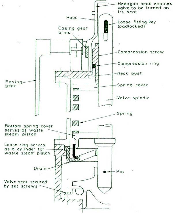
IMPROVED HIGH LIFT SAFETY VALVE
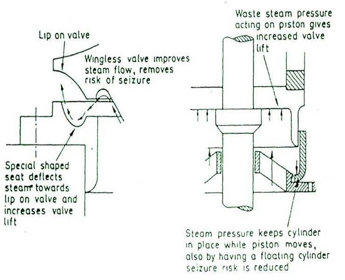
FULL LIFT SAFETY VALVE (for pressures up to 63 bar)
FULL BORE RELAY OPERATED SAFETY VALVE
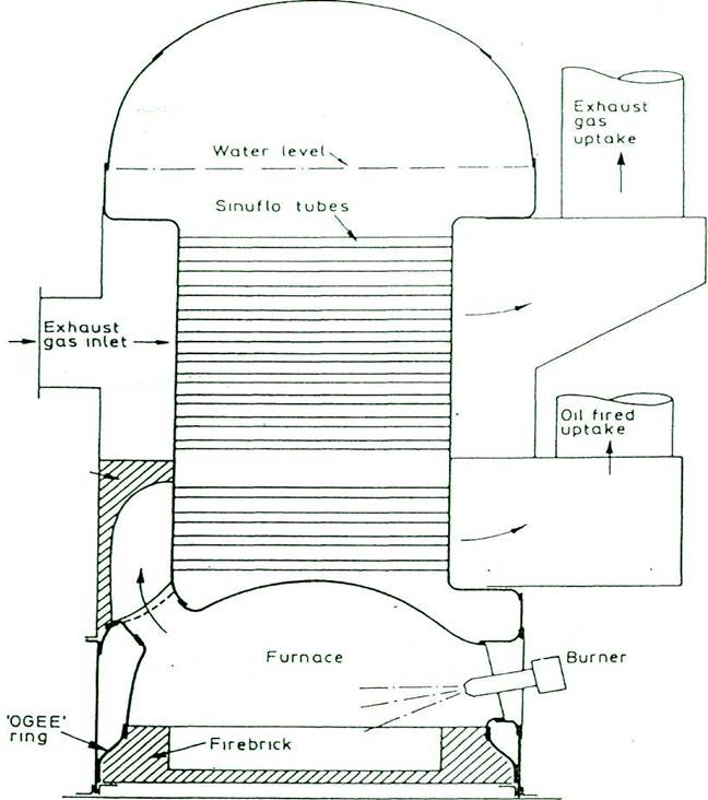
DIAGRAMMATIC ARRANGEMENT OF A SINGLE PASS COMPOSITE COCHRAN BOILER
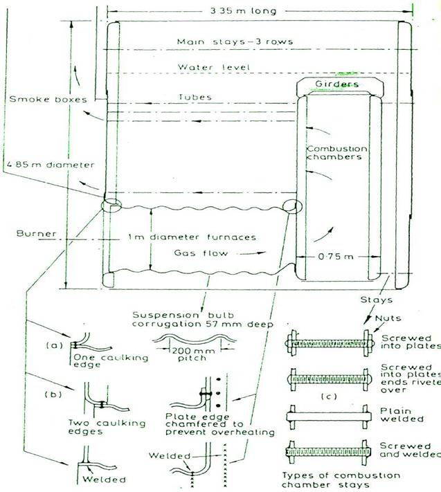
SCOTCH BOILER
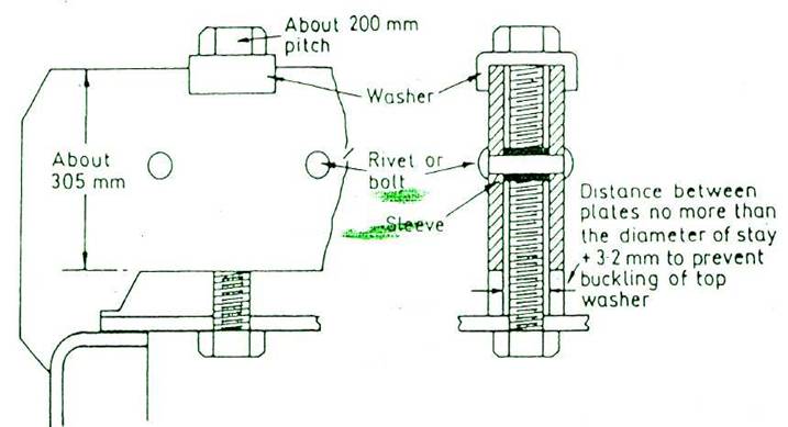
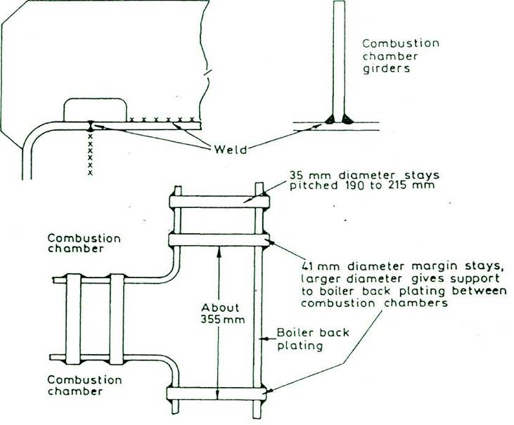
SCOTCH BOILER
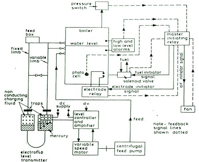
AUTOMATIC BOILER CONTROL SYSTEM
FUEL/AIR RATIO CONTROLLER OF BOILER COMBUSTION
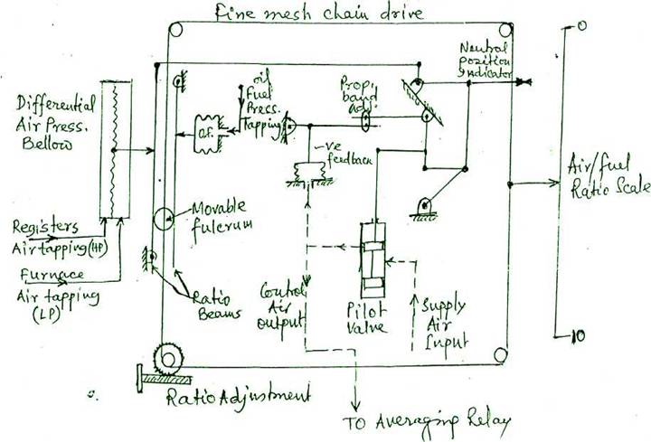
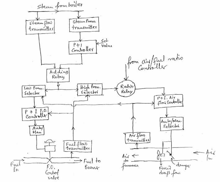
Change in combustion air flow between air register and furnace air, is measured in terms of the movement transmitted of a large bellow and applied to the ratio beam. Change in fuel oil pressure, caused by the master pressure controller due to variation of steam pressure, is fed to smaller O.F bellow and applied to another ratio beam. These two signals are in opposition when applied to the beam system. Between the beams there, is a movable roller fulcrum, the movement of which by the ratio adjustment screw, gives different equilibrium conditions and the ratio is indicated on the fuel/air ratio scale. Beam lever position operates a linkage to the pilot valve which varies control air output signal. Beam lever movement controls the pilot valve position by proportional action having proportional band adjustment and negative feedback arrangement. Input air to the pilot valve is controlled by the position of pilot valve pistons according to the fuel/air ratio setting. This output air signal is fed to the averaging relay of automatic combustion control system where it 'trims' the signal being fed through to the air damper actuators. The correct fuel-air ratio can be maintained irrespective of the numbers of burners in use provided that air register are closed on burners which are not in use.
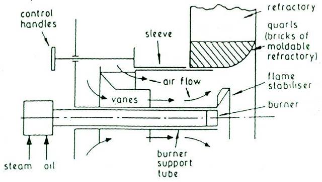
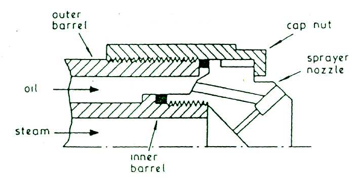
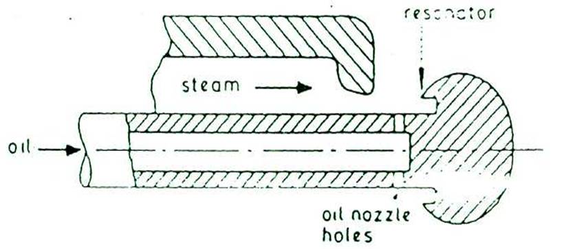
STEAM ATOMISING EQUIPMENT