CENTRIFUGE
Instead of making use of gravity to cause separation, the centrifuge uses centrifugal force, which is much greater. The ratio of centrifugal force to the gravitational force is often referred to as the 'G' value, which depends on the rotational speed and design of the centrifuge and is in the order of 7000-9000.
Marine centrifuges can usually be set up to operate in two mods ; as a clarifier or as a purifier. When operating as a clarifier, there is only one outlet, which is for fuel oil, but when operating as a purifier there is an additional outlet for the discharge of water.
PRINCIPLE OF OPERATION
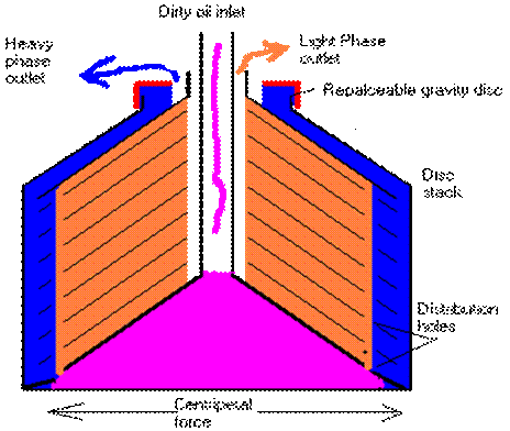
In the purifier set up to separate water as well as solids from oil, water is introduced at the begining into the bowl, via the central feed pipe. Centrifugal force makes this water form a rotating ring at the bowl periphery, the inner vertical wall of this water ring is inside the edge of the top disk.
When the water seal has been established, the oil feed is introduced and separation starts.
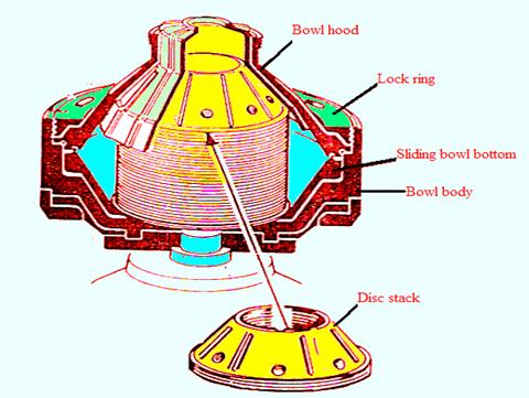
When the bowl is rotated, centrifugal force will throw any item with a density greater than oil density (the solid matter and free water) to the periphery of the bowl. The efficiency of the centrifuge is increased by the inclusion of a number of discs, which have the effect of increasing the surface area to aid separation. These discs are separated a distances of 0.5-0.6 mm by a series of caulks fixed to-the upper side of the disc.
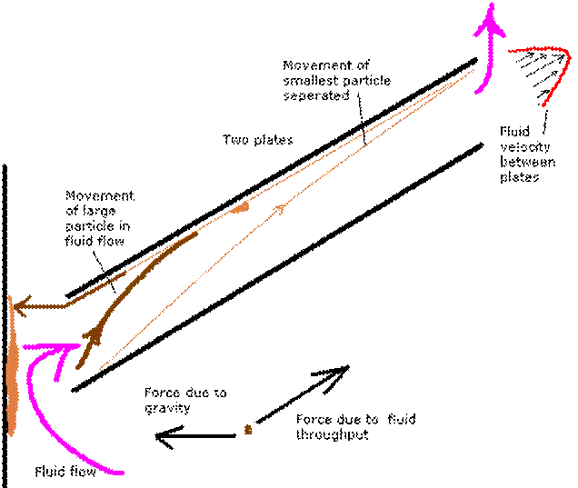
After passing down the central passage, the untreated oil is carried by centrifugal force towards the periphery of the bowl and then passes up through the disc stack. It is here that the actual separation takes place, in the channel formed between two discs. In this channel, the velocity of oil is greatest at the centre and zero at the disc surface. Each particle, solid or liquid, is .acted upon by two forces. On the one hand, the particle is being forced upwards with the oil stream towards the centre (W), whilst on the other, centrifugal force is directing it to the periphery (V). It is the resultant of these two forces which determines the path of the particle between the discs (VP). In order to be separated out, the particle must be deposited on the upper disc (B-B1 in fig), that is at a radius greater than on or equal to r2. The particle is considered to have separated out on reaching the disc stack surfaces and as the liquid velocity is negligible close to this surface, the particle moves outwards by centrifugal force towards the periphery of the bowl.
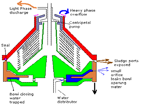
In both modes of operation of centrifuge, as a clarifier or purifier, the particulate matter will be collected on the wall of the bowl and if no corrective action is taken, will continue to build up to such an extent that it is at radius r1 the outer radius of the disc (see fig) and obstruct flow through the centrifuge. In self cleaning centrifuge, auto-desludging arrangement is provided to discharge the bowl content intermittently whilst the centrifuge is still in operation.
For the fuel oil purifier, the untreated oil is a mixture of oil, solids and water which the centrifuge separates into three layers. Whilst in operation, a quantity of water remains in the bowl to form a complete seal around the underside of the top disc and because of the density difference, confiues the oil within the outside diameter of the top disc. As marine fuel oil, normally only contains a small quantity of water, it is necessary to prime the bowl each time it is run, otherwise all the oil will pass over the water outlet side to waste. The water outlet is at a greater radius than that of the fuel and within the water outlet, there is a gravity disc, sometimes referred to as a dam ring, which controls the radial position of the fuel/water interface. The optimum size of the gravity disc to be filled depends on the density of the untreated oil. If the internal diameter of the gravity disc is too small, the separating efficiency will be reduced as the interface will be formed within the disc pack. If the internal diameter is too large, the interface will form at a diameter greater than the top disc, and oil will pass to waste through the water outlet.
In addition to the density ratio between the oil and water, there are other factors which can influence the position of the interface. These are viscosity flow rate and variation in density. A decrease in viscosity, due to an increase in temperature a decrease in flow rate, a decrease in back pressure or a decrease in density will result in the interface moving inwards. Conversely, an increase in viscosity due to a decrease in temperature, an increase in flow rate, or an increase in density, will move the interface outwards, ultimately resulting in a loss of the liquid seal. The optimum position of the interface is between the edge of the disc stack and the outer diameter of the top disc.
THE PARING DISC
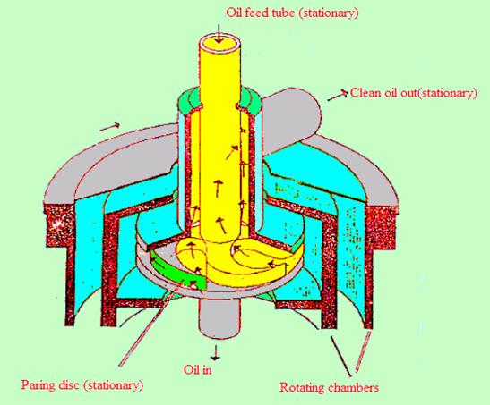
Some centrifuges are fitted with a manually operated interface control device in order to reduce the frequency of changing the gravity discs as a result of changes in density from different bunkerings. This device is fitted at the top of the centrifuge, to ensure a pressurised oil discharge, (see fig.)
The arrangement is a stationery paring disc discharge pump impeller mounted in a chamber, for the treated oil. The impeller blade's dip into the rotating ring of oil and scoop it out, converting the kinetic energy of rotation into pressure head. It also consists of a pressure balanced valve, fitted into the discharge line. By applying a counter pressure to the discharge line, the interface can be moved outside the disc stack without changing the gravity disc.
This feature, however, does not replace the requirement for effective control of throughput and temperature.
For a vessel operating on residual fuel, the generally recommended practice is to operate two machines in series. The first machine should set as a purifier, and the second as a clarifier. This arrangement improves overall separation efficiency and the clarifier provides a safety margin if the purifier is not set for optimum performance. This safety margin is beneficial in the treatment of high density fuels, when the purifier is operating near to the limit of its performance.

SELF CLEANING CENTRIFUGE
