SIMPLEX TYPE STERN TUBE:
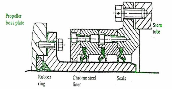
In Simplex type oil lubricated stern tube, the tube is fitted in the stern frame with an elongated boss to provide better support for the white metal lined bearing. A minimum bearing length of two times shaft diameter will ensure that bearing load does not exceed 0.8 N/mm2. The bearing bush is normally grey or noduler cast iron centrifugally lined with white metal. A typical analysis of white metal would be 3% copper, 7.5% antimony and the remainder tin. White metal thickness varies according to the classification society. 3.8 mm for a shaft of 300 mm dia to 7.4 mm for a 900 mm dia shaft with bearing clearance of 0.51-0.63 mm to 1.53-1.89 mm respectively. The forward part of the stern tube is fabricated and welded direct to the extension of the stern frame boss and into the aft peak bulkhead. Oil pressure within the stern tube is maintained at approximately the same level as that of the surrounding sea water by a headertank. Oil is contained within the simplex type stern tube by Lip Seals. The elastic lip of each nitrile rubber seal, grips a rubbing surface provided by short chrome steel liners at outboard and inboard ends of steel propeller shaft. The outboard liner additionally protects the steel shaft from sea- water contact and corrosion. Heat produced by the friction will result in hardening and loss of elasticity of the rubber, should temperature of the seal material exceed 110°C. Cooling at the outboard end is provided by sea water. Inboard seals are cooled by oil circulation and convection. Connections for circulation are fitted top and bottom between the two inboard seals and the small local header tank. The chrome liners act as rubbing surfaces for the rubber lip seals but grooving from frictional wear is overcome by using a ceramic filler for the groove or alternatively a distance piece to displace axially the seal and ring assembly. Allowance is provided for the relative movement of shaft and stern tube due to differential expansion. New seals can be fitted by cutting and vulcanizing in position. A lip seal assembly consists of 3 rings in the aft seal and two rings in the forward seal. Seals are made of nitrile rubber rings of special cross-section, sandwitched between bronze rings. In the case of aft seal, the outboard sealing rings have their garter springs located aft of the ring anchoring bulbs while the inboard ring has its garter springs located inboard of the anchoring bulbs. In case of two forward seal rings, the garter springs holding the searing rings against the shaft is located aft of the ring anchoring bulb. In some instances four or more sealing rings are installed. In the event of leakage from the working seals, adjustment is made to bring the reserve ring into play. In the latest model "Leak Proof option, there are two void spaces in each gland circulated with oil, the oil being changed several times per hour by a circulator. Any water ingress is settled out and draimed. The oil circulation is at a pressure slightly less than the outside sea water pressure, hence pollution can not occur. This model is claimed to overcome the problem of the centre seal of the aft gland failing due to high temperature deterioration. A gravity tank for the lubrication of stern tube must be so arranged that when the ship is running loaded or in .ballast, the oil pressure amounts to only 0.2 to 0.3 Kg/cm2 more than the outside seawater pressure. The distance 'h' (mtr) between the load or ballast waterline and the oil level in the gravity tank, is ascertained according to following formula :-
H- 0.165 H/2.8 mtr, here "H" (m) is the vertical distance between propeller shaft centerline and load or ballast water line. Where H (m), the vertical distance greater than 14 mtr, a second gravity tank must be fitted for the relief from time to time of the sealing rings when the ship is running in ballast.
Simplex Type Stern Tube Seal:-

Lip seal assembly
Spheroidal cast iron stem tube is fitted inside the stern frame at the aft end and supported at the aftpeak bulkhead at the forward end. White metal centrifugally lined modular cast iron bearing bush of length two times shaft diameter will ensure that bearing load does not exceed 0.8N/mnT.
White metal composition 3% Cu. 7.5% Sb & remainder Sn. Typical white metal thickness - 3.8 mm for shaft dia of 300 mm 7.4 mm" " " " 900 mm. Bearing clearance 0.51 to 0.63 mm - 300 mm dia shaft. 1.53 to 1.89 mm - 900 mm dia shaft.
Chrome steel liners are fitted on the shaft at the outboard and inboard end to protect the shaft from sea water and also from wear with lip seals. Nitrile rubber lip seals are provided to prevent oil leakage. Chrome liners acts as rubbing surface for lip seals.
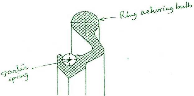
3 lipseals are fitted between bronze rings at the aft end. Two outboard lip seals have their garter springs located at the aft of the ring anchoring bulbs while the 3rd inboard seal has its garter spring located inboard of anchoring bulbs. Whereas for two forward lipseals. the garter springs holding the sealing rings against the shaft are located aft of the anchoring bulbs.

Nitrile rubber ring cross-section
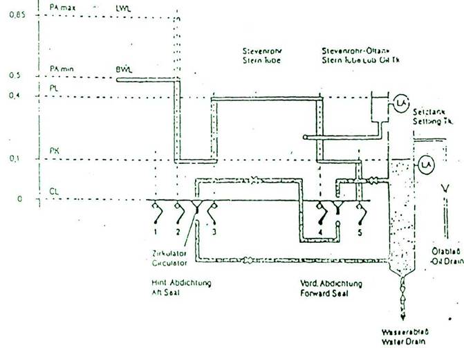
Leakproof System :-

The 'Leakproof option comprises an oil filled annular space at low static oil pressure in the aft seal.
Between 2nd & 3rd sealing ring pressure of settling oil tank(0.1 bar) PK is maintained which is below ballast water level(BWL) and also below the stern tube oil pressure level (PL).
A pressure differential of 0.3 bar is found satisfactory with this system, any leakage from either sea water or lub.oil is taken up in the annular space between lip seals 2 & 3 , thereby increasing its level in the settling tank. An alarm signal monitors any increase in setting tank level. A leakage of water can be dealt with by draining off whereas leakage of oil can be taken back to stern tube oil tank. Worn chrome liner can be skimmed by about 4.8mm on an original dia of 1000mm. The springs must be shortened by 3mm per lmm reduction in clia of shaft.