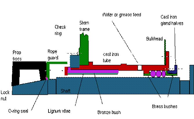
Oil lubricated Stern Tube Bearing : -
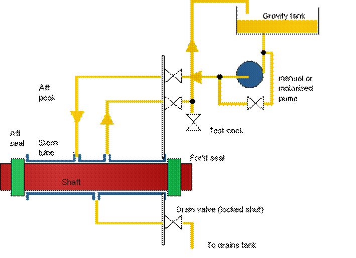
The cast iron stern tube is fitted inside with a white metal lined bronze bush and the ends ( propeller end and forward end) of the tube are sealed with a gland. Oil supply under pressure keeps the friction minimum. The weardown for the white metal should not normally exceed 2 mm to avoid hammering out and the period between inspection is about six years. Any leakage of water into the oil should be regularly drained off. A highly resilient reinforced plastic material is often used in place of white metal. It is claimed to have superior load carrying capacity, high resistance to fatigue and shock loading with good lubricating properties. Stern tube seals, with oil lubrication have also tended to use rubber rings increasingly. Fluoric rubber (Viton) with additives bas been shown to be more effective than nitrile butadiene rubber for seal rings. In these designs, four seal rings are usually located in the support housing aft with oil pressure supply to middle chamber. Two similar ring seals, with oil feed between, are arranged in a floating housing at the forward end. Ceramic coated liners are also used.

COUPLING BOLTS :
For transmission of torque by flanged coupling in main propulsion shafting, two factors are to considered -
(1) Coupling bolts are tightened to a specific value of stress to force the faces of the flanges together, such that full surface contact takes place and the friction between the faces will provide some proportion of the drive.
(2) Perfect interference fit between bolt shanks and the flange holes for maximum transfer of load. The number of bolts is designed to carry the torque in shear. The elongation of a bolt when tightened causes a reduction in cross-sectional area. The relationship between change in length and the change of cross-sectional area, is summarized by Poisson's Ratio. A normally fitted bolt when tightened, the positive contact between the accurately machined bolt and the reamered hole is lost, because of the elongation of the bolt. Moreover fretting can also cause damage to bolt. An oversize bolt may be used and cooling of the shank-probably with liquid nitrogen -would be necessary to cause contraction and reduction of cross-sectional area before insertion. But the effect of low temperature and the probability of steel becoming brittle as a result of cooling is a potential danger. For parallely fitted bolts, slackness due to elongation can cause ovality of flange bore, reduced contact surface between coupling bolt shank and flange bore hole surface causes fretting. There can be effect of "spot facing" misalignment which can cause additional bending stress on the coupling bolts. No. of coupling bolts and their diameter are obtained from prescribed formula based on the torque to be transmitted. The flange thickness should be at least equal to bolt diameter. Propeller shaft coupling flange thickness should be at least 0.27 x shaft diameter and fillet radii on shaft should be 0.08 x shaft diameter. In all cases, shafting, coupling and bolts must provide resistance to astern pull. A tapered coupling bolt could be used instead of a conventional parallel fitted bolt to obtain a good fit and the required tightening.
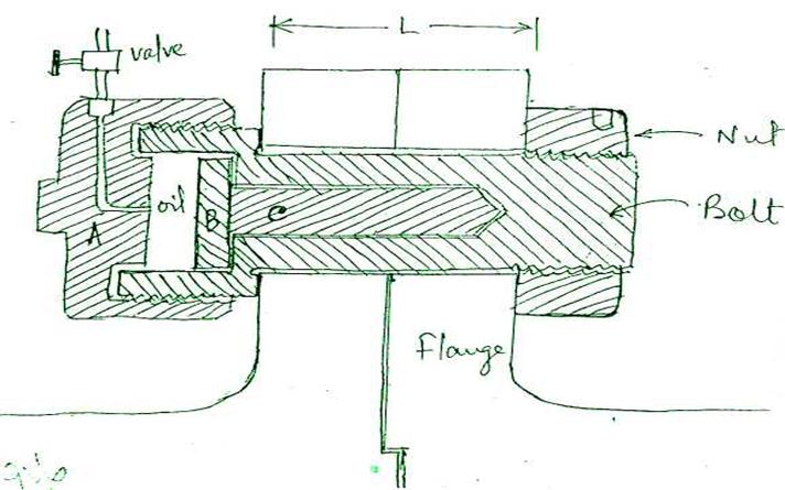
(3) The Pilgrim hydraulic bolt uses the principle embodied in Poisson's Ratio to provide a calculated and definite fitting force between bolt and hole. The bolt is hollow and before being fitted is stretched with hydraulic pressure applied to an inserted rod from a pressure cylinder screwed to the bolt head. Stretching makes the bolt diameter small enough for insertion into the hole, after which the nut is nipped up. Release of hydraulic pressure allows the bolt to shorten, so that (i) predetermined bolt load is produced and (ii) diametrical re-expansion gives a good fit of the shank in hole.
These bolt can easily be removed for inspection and maintenance by applying hydraulic pressure to slacken the nut and the slackened bolt comes out easily.
To Tighten :-
(l)Boltdia=D + 0.00025D
(2)Hydraulic
pressure applied 30,000 lb/in2 and valve shut-off. Bolt
length increases by
0.002L and diameter reduces by 0.00025D.
(3)Bolt is now placed in the flange hole by hand.
(4)Nut is screwed on to the bolt and nipped up with claw spanner.
(5)Hydraulic
pressure is released by opening valve. Bolt diameter expands into
flange
hole with tight fit and shortens to provide 15.5ton/in2
tensile load.
(6)Items A, B & C are removed.
(7)Depth gauge is used to measure the residual strain on the bolt.
To Slacken off:- (1) A,B & C are refitted.
(2)Hyd. Press 30,000 psi is applied.
(3)Nut is slackened off and bolt is removed.
NOTE :- Loss in shear area due to hollow section is allowed for in the material by proper alloying.
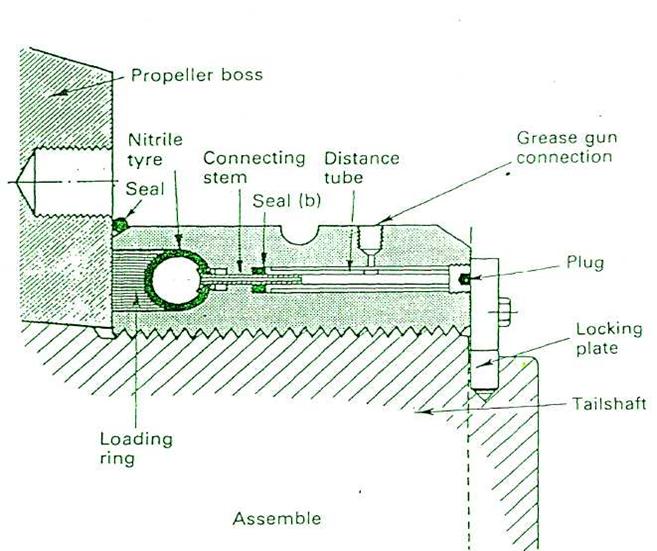
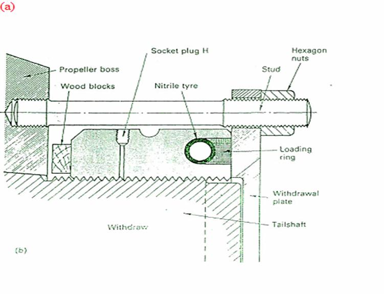
PILGRIM NUT
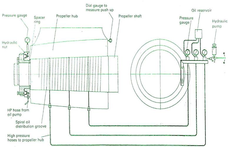
Oil injection propeller mounting
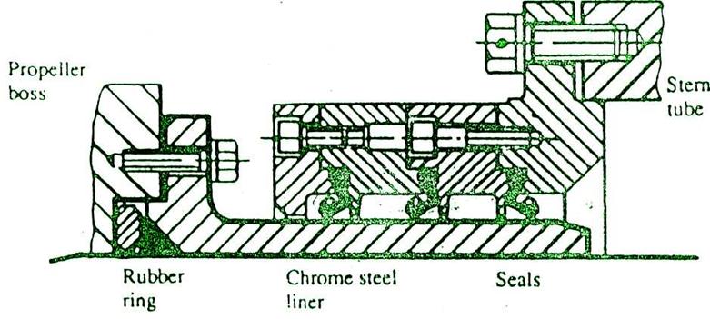
Lip seal assembly
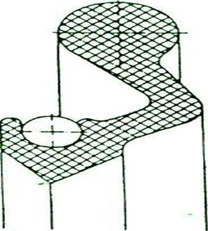
Nitrile rubber ring cross-section
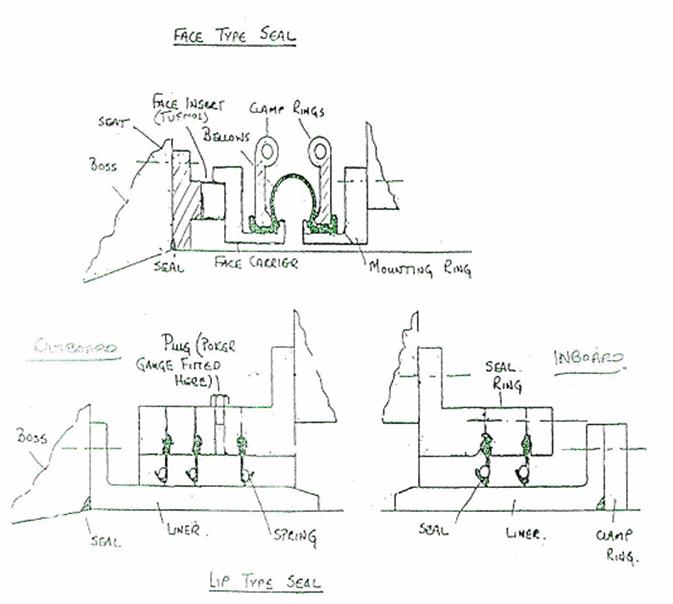
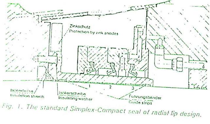
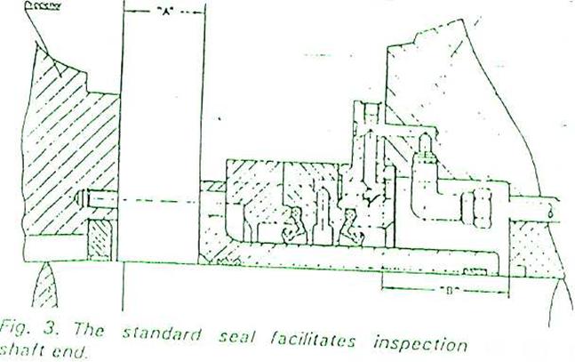
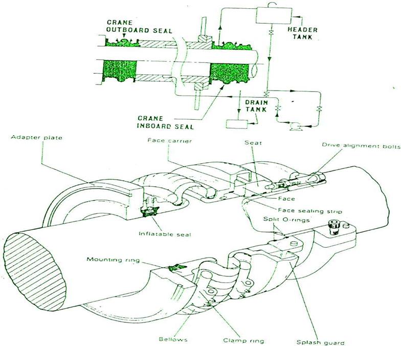
Figure Example of a radial face seal (Deep Sea Seals Ltd.)