Propeller material :-
Cast Nikalium :- Copper - 80.2%, Aluminium -9.3% Nickel-4.3% Iron-5.0% Manganese - 1.2%
Mechanical properties
Tensile properties - 0.2% proof stress - 27.4 Kg/mm2 Tensile strength - 70Kg/mm2, Elongation -27%
Propellers as large as 100 tonnes can be cast in nikalium, the blades having a thickness of 0.5 m at the root. The most important property affecting the life of propeller is corrosion fatigue resistance.
Corrosion Resistance: The sea water corrosion rate of nikalium is negligible. Under certain conditions, however, copper based alloys suffer from wastage. This is an impingement attack which occurs in regions of high velocity water flow and leads to dissolution of metal. Nikalium is considered to be three times more resistant to this type of attack than manganese bronze.
Cavitation Erosion : This is caused by excessive wake inequalities due to the hull form at the stern of the vessel. If these inequalities cannot be reduced to acceptable limits, the resulting cavitation will lead to erosion of the blade surfaces. Nikalium has a high resistance to this type of attack.
Propeller efficiency : The function of the propeller is to absorb the power delivered by the main engine at the revolution and to produce maximum thrust and so maximum ship speed. The efficiency of the propeller is given by the thrust power divided by the delivered power at specific revolution.
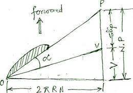
Propeller slip :- Advancement of the propeller for one complete revolution is called the propeller pitch. Since the propeller works in water and due to its fluidity, it advances a distance somewhat less than its pitch. The difference between these distances is called the slip.

If the velocity is at right angles to the direction of advance, it is plotted as 2piRN. If the ship speed V is plotted in the direction of advance the resultant water flow will be along the line OV. The attitude of the blade is defined by the pitch and revolution and thus for a given propeller the angle of incidence is defined by the ship as shown. Slip is expressed as a percentage of the pitch (P) and if a propeller rotates at N RPM and the forward speed is V Knots, then

Apparent slip is obtained by using the measured ship's speed in association with the propeller revolution. In general, the speed of the propeller disc is less than ship's speed. The difference is due to the factional effect of the ships hull slowing down the water passing the ship, and is called the "wake Speed". The mean speed of the propeller relative to the surrounding water is called the speed of advance Va. Ship Speed, Va= Vs (1-Wt) where Wt is the wake friction. Real slip is calculated using this speed of advance Va and is always greater than apparent slip.
Propeller Surface Roughness :-
During normal service at sea, roughness of the blade surface occurs and can be attributed to the following :-
a) Marine growth :- Marine growth of the animal and vegetable variety forms on propeller blade surfaces when the propeller is stationery. The attachment of barnacles results in a loss of propeller efficiency, an increase in absorbed

power and a lower rev/min. when the vessel returns to service, the action of water may remove some of the barnacles, but the surface does not return to normal until the propeller is properly cleaned.
b) Impingement attack:-
Impingement attack usually occurs at the leading edges and outer parts of the propeller blades where circumferential velocities are highest. The effect on the blades is a large area of surface roughness of shallow depth.
c) Corrosion attack ;-
Chemical and electro-chemical corrosion due to galvanic action between dissimilar metals can be minimized by the use of cathodic protection system.
d) Cavitation erosion :-
Cavitation occurs when a drop in pressure at the leading edge and on the surface of the suction side is sufficient to produce vapour from the liquid. These vapour pockets and bubbles when subjected to positive pressure collapses and collapsing of the bubbles cause impact damages on the blade metal surface. This can be avoided by supercavitating hydrofoil blade section design.
e) Bad Maintencance:-
Grinding of the blade surfaces by inexperienced operators using grinding discs that are two coarse can accelerate surface roughness.
Roughness
Measurement: There are two main methods
of roughness measurement: peak to valley average(PVA) and centerline
average(Ra). There is no direct relationship between the two
measurements. International Standard
Organisation recommends that
ship's propellers be manufactured to class I tolerances, giving a
surface finish of better than 3![]() m
Ra. Surface
finish to below l
m
Ra. Surface
finish to below l![]() m
Ra can be achieved, but the cost of producing this finish is not
considered to be economical as the superfine finish can be quickly
reduced in service. A portable instrument which measures the surface
condition by using a comparator gauge gives direct readings of mmRa.
m
Ra can be achieved, but the cost of producing this finish is not
considered to be economical as the superfine finish can be quickly
reduced in service. A portable instrument which measures the surface
condition by using a comparator gauge gives direct readings of mmRa.
Maintenance & Repairs :-
a) Roughness due to corrosion around the blade tips can be ground out and polished to its original condition
b) For pitting of upto lmm in depth, the grinding and polishing operation is also successful.
c) If time is of the essence, the roughness can be temporarily removed by use of synthetic resin fillers.
d) Small tears, cracks and local edge deformation should receive attention as quickly as possible.
e) Deformed leading edges create conditions of disturbed flow or turbulence over the blade surface which causes an increase in general wastage or severe cavitation damage. Minor repairs may be done in place but for more serious damage requires removal of the propeller.
Propeller Repairs :-
In general, repairs fall into three categories -
a) Straightening of distorted blades: The damage area is slowly and uniformly heated to the correct temperature, straightening of the deformed blade can be achieved by the use of weights and levers to its original pitch and track. Cooling should also be slow to avoid the creation of internal stresses.
b) Welding - For Nikalium propeller, an inert gas shielded metal arc process of welding is generally preferred. If flux coated electrodes are used, they should be preheated to 120°C for approximately 1 hour. All slag should be removed between consecutive weld runs. No preheating of the area to be welded is necessary because of the possible introduction of cracking. If an area has been repaired before, the original repair should be removed before attempting a new repair. If the propeller is made of other alloys, the manufacturer should be consulted regarding the type of electrode to be used and any post-weld stress relieving process which may be required.
c) Burning-on: Missing portions of blades can be replaced and small cracks repaired by cutting them out and fusing in new metal. Care should be taken in selecting the material to be used and the electrodes, as incorrect selection can lead to eating away of weld metal, and replaced part of the blade falling off. The above repairs can be carried out on the outer parts of the blade but should not be done inside 0.45 of the radius of the propeller. All repairs to be carried with the approval of classification society surveyor and by approved operator.