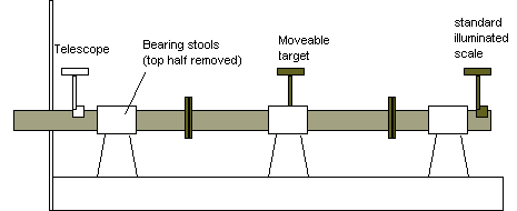
SIGHTING BY LIGHT METHOD (OPTICAL TELESCOPE) –

Reference datums are selected at height of the shaft above the keel aft and the height of the crankshaft centre above the keel extended to the forward machinery space bulkhead (also centre athwartship) forward. These two datums are taken from the ship drawings.
The rough bore of the stern frame is fitted with a plate flange having a small hole of sight holes say 800 pm max error 16mm le 1mm per say 40m length elevation
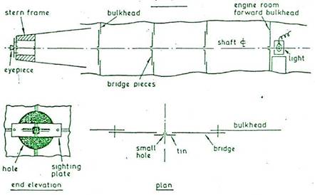
SIGHTING BY LIGHT
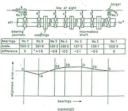
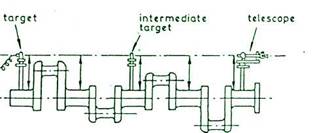
telescope micrometers allow variation of ±100 mm on perpendicular crosslines but the radial markings on the telescope which are graduated up to 25 mm diameter allow much greater misalignment to be read directly from target without using micrometers at all
SIGHTING BY OPTICAL TELESCOPE
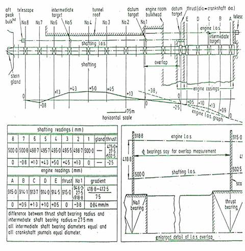
SIGHTING IN SHIP
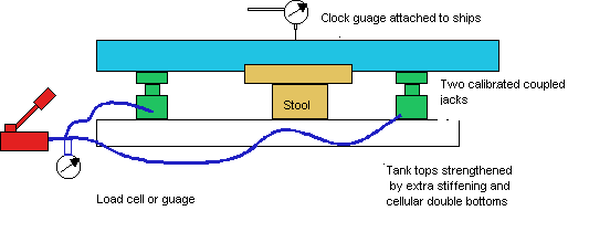
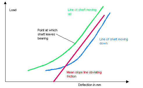
Top cover off and horizontal alignment checked by measuring the side clearances of the shaft within the bearings. By using the system shown the shaft is carefully jacked up and a graph plotted. Initially a curve will be plotted as the ships structure stress relieves itself from the weight of the shafting, shaft still sitting on bearing material.
When curve assumes a straight line shaft has left bearing and in order to avoid damaging the shaft only sufficient plots will be taken to establish the slope of the straight line. The slope of the line for each bearing is put into a computer program which establishes the shaft system characteristic.
