FAIR CURVE ALIGNMENT:
The method of fair curve alignment accepts the changes of line endured by the shaft system and seeks a compromise installation to suit the varying conditions.
The initial calculation is to determine the load on each bearing, assuming all bearings to be on a straight line datum, done by a computer. The computer programme then simulates the raising of each bearing through a range and calculates, for each smai! change, the increase of its own load and alteration in load on each of the other bearings. The process is then repeated with a simulation of the lowering of each bearing in turn with the computer finding.resultant load change on the bearing in question and the others. Influence Numbers, in terms of load change for each height variation, are calculated by this exercise for all bearings. The Influence Numbers express the change in load over unit changes in vertical movement (Newton/mm) for each bearing in the system and also give the effect of raising one bearing will have on the other bearings.


The data bank of influence numbers enables the effect of changes in alignment from hull flexure and local factors to be found. All of the variables are assessed to determine the best compromise for shaft installation. The designers use this data to obtain a shaft line that is a smooth (fair) curve that allows for a slope at the stern bearing and an acceptable bending moment line up to the engine coupling.
The method of jacking the shaft to assess corrected bearing loads, is used as a realistic means of ensuring that statically, the shaft installation is satisfactory. In simple terms load on each bearing can be stated as total weight of the shaft divided by the number of bearings.
The procedure involves the use of hydraulic jacks placed on each side of the bearing, to lift the shaft just clear. A dial gauge fixed to the bearing, indicates lift. Hydraulic pressure exerted by the jacks, registers the load on the bearing.
A plot of lift and load while hydraulically lifting the shaft, shows a distintive pattern, due to the elasticity of the steel and removal of deformation from the bearing.
As the hydraulic jack pressures are raised from zero, the concentrated loading initially causes deformation of the shaft. Only after the journal section has been bowed up out of shape to some degree, and the bearing material resumes its relaxed primary shape, does the sagging centre part of journal lift clear and out of contact with the bearing. The plot shows that the dial gauge register upward movement as soon as the shaft is pushed out of shape by increasing hydraulic pressure. The curve takes different shape as the shaft lifts clear.
If the jacking is taken too far, then adjacent bearings gradually become unloaded and the plot is affected by a change in elastic system. To guard against this dial gauges are fixed on adjacent bearings to ensure that the lift is limited to the bearing that is being checked.
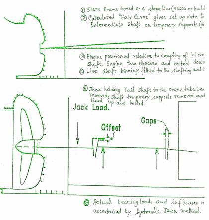
The final analysis is carried out on this fair curve shaft line. This gives the loads on each bearings, shear forces in the shaft, bending moment in each shaft section and most importantly, setting-up data for the shafting. Using this data, the stern frame is bored out and after the launch of the ship, the shaft system is installed. The shafting system installation works from the tail shaft as a datum. The final part of this process is setting the engine bedplate at the correct height and altitude.
During the installation of the shaft and engine, the shaft system is supported on temporary supports and the couplings are set with gaps and offsets that are the result of final shaft analysis. The gaps and offsets are calculated to give the reguired fair curve when the couplings are aligned by insertion of feelers between couplings to correct the alignment.
After the engine is finally chocked and bolted, the shaft bearings are positioned. The shaft couplings are brought into line and the coupling bolts fitted, after aligning with feelers.
The final line of the shafting is the smooth curve reguired for optimum bearing loads when the ship is in service

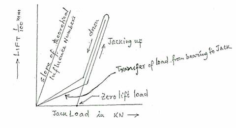
The shaft is raised in increments, with the Jack load and the corresponding lift being recorded and plotted. This will show two distinct slopes, the gradual slope is when the bearing load is being transferred to the hydraulic jack and is the "spring constant" for the seating, bearing and housing.
The steeper slope is a measure of bearing Influence Number (lift per unit force, this should show a relationship with the calculated influence number.
Extrapolating the steeper slope back to the zero-lift position gives the actual bearing load (load at zero lift).
