RUDDER CARRIER BEARING:-
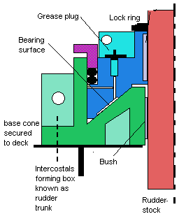
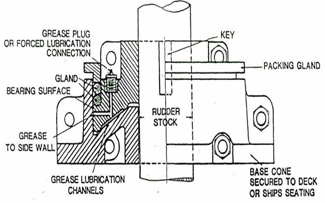
The rudder carrier bearing takes the weight of the rudder on a grease lubricated thrust face with a conical seat. The advantage of conical seat over flat face is that the seat and the side wall locate the rudder stock. The angle of the conical seat is shallow to prevent binding. Bearing weardown occurs over a period of time and allowance is made in the construction of steering gear for a small vertical drop of rudder stock.
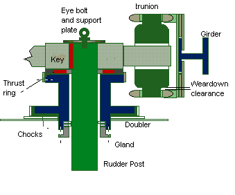
Weardown of the carrier bearing is monitored periodically measuring the clearance by original gauge( U- shape with pointed edges) which is normally of size 16-19 mm between two punch marks. Lifting of the rudder and stock by heavy weather can be limited by jumping stops between the upper surface of the rudder and the stern frame. Similar lift clearance of 6 - 9 mm is also allowed between swivel bearing and ram crosshead at the rapson slide mechanism with the tiller arm. The usual limit for movement of the rudder, is 35° each way from the mid-position and this is controlled by the telemotor. Support for the carrier bearing is provided by framing beneath the steering gear deck .
There is thicker deck plating in the area beneath the carrier bearing and the latter may be supported on steel chocks. The base of the carrier bearing is located by side chocks welded to the deck. The carrier bearing may be split in two parts for removal or replacements. Screw down hand lubricators or automatic lubricators are fitted and the grease used for lubrication is of a water resistant calcium soap base with graphite.
The tiller arm is keyed to the rudder stock and is of forged or cast steel with one or two arms (two or four ram gear), machined smooth to slide in a swivel block arrangement designed to convert linear movement of the rams to the rotary movement of the tiller arms and rudder stock. The rams are one-piece steel forgings, with the working surface ground to a high finish. Each pair of Rapson slide rams, is bolted together , the joined ends being bored vertically and bushed to form top and bottom bearings for the projecting spigots on the swivel block. Crosshead slippers, bolted to the face of the central section of. the rams, slide on the machined surfaces of the guide beam. Guide beams also serve to brace each pair of cylinders against the tendency for them to be pushed apart by the hydraulic pressure. The cylinders have substantial feet bolted to the stools on which the gear is mounted.


Carrier with conical seat