HYDRAULIC TELEMOTOR SYSTEM
Hydraulic Telemotor System when operated by auto-pilot works on closed loop control principle.
The telemotor itself employs a 'master' and 'slave' with the transmitter at Bridge as master and receiver at steering compartment as the slave. Mechanical movement is transduced hydraulically for distance telemotoring and then transduced back again in a closed loop.
Hydraulic Transmitter:
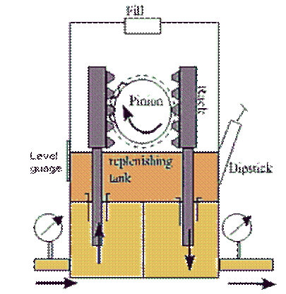
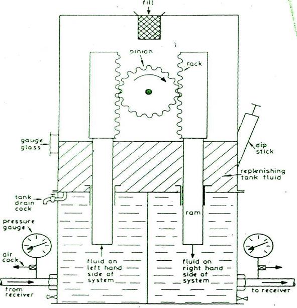
The transmitter consists of a cylinder with a pedastal base which contains two rams operated by rack and pinion from the steering wheel. Transmitter and Receiver are connected by solid drawn copper pipes, casing is usually gun metal with bronze rams. As the bridge steering wheel is moved to starboard, the rotating pinion causes the right hand ram to move down, pushing oil out to receiving unit along the right hand pipe. The left hand ram moves up, so allowing a space for oil to come from the receiving unit. The make up replenishing tank acts as an oil reservoir and functions automatically through spring loaded relief and make-up valves. Excess pressure in the telemotor system causes oil to be released through the relief valve (set at 18 bar) to the make up tank and loss of oil is made up through the lightly loaded make-up valve. The two valves are connected through a shutoff valve, which is normally kept open and the bypass which connect both sides of pressure system, when the piston is in mid-position, the tank must always be kept topped up and non-freezing working fluid of low viscosity and pour point should be used.
Bypass Valve :
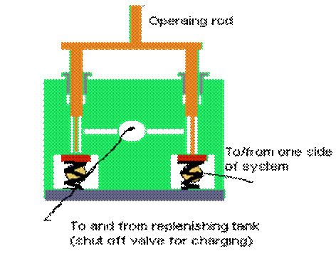
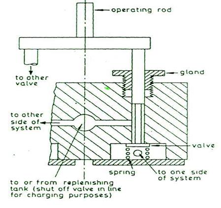
The bypass valve has the function of topping up the system in the case of leakages and acting as a relief valve in case of pressure rise for variation in volume of oil due to temp, changes and also to allow for equilibrium between both sides of the system. In mid-position of the steering wheel, the operating rod gets depressed by a circular disc operated by a cam which connects both sides of the system by operating the bypass valve for pressure balance. The connection to the replenishing tank also joined to both sides of the system, so that any expansion or contraction of the oil can be corrected. To test most gears for tightness, the wheel can be lashed over, first one side then the other, at a pressure of about 42 bar (which should hold for a considerable time). Leakage at either side means that all pipe joints and glands must be examined. To test the bypass valve, the procedure is repeated but with the liquid saving (or circuit valves) on the receiver telemotor shut, this loads each of the valves on the bypass unit in turn.
By-pass valve

HYDRAULIC TRANSMITTER.


BYPASS VALVE (1\2 VIEW)
Hydraulic telemotor Receiver :
The receiver consists of two receiving cylinders in one casting with the circuit pipes connected to the outer end of each ram. Any fluid displaced in the transmitter cylinder by the piston will therefore be forced through the pipes and circuit valves to the receiving cylinder . The receiver rams are fixed in the arrangement and any displacement of the fluid causes the cylinder body to move along the ram against the compression of one of the springs. The compressed spring serves to return the receiver and with it the transmitter to midship position when the helmsman release the steering wheel. The linkage of the pump control through the hunting lever is fitted to one end of the cylinder body.
POWER AMPLIFIER UINTS :-
The function of the power units is to amplify and transduce the receiver telemotor output signal, in the correct direction, for transmission to the final controlling actuator operating the rudder.